
Schematic


RS-485 WIRELESS BRIDGE USER’S MANAUL REV. 02 5
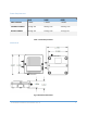
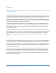
The mechanical dimensions for the wireless bridge are shown in Figure 1. The mechanical dimensions
are shown with the optional DIN rail mount bracket which is not included with the standard part
number. Mechanical data for the antenna is not shown.
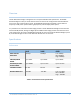
Pinout and Wiring
The RS-485 Wireless Bridge uses RS-485 2-wire mode by default. In a normal 2-wire scenario only pin 1
(T/R+), pin 2(T/R-) and pin 5 (Signal GND) are used. The RS-485 Wireless Bridge can be set up to use 4-
wire mode. Also, the device can be configured to use an internal termination resistor if needed.
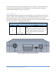
Commands and examples are given in the configuration section of this manual. Figure 2 & Figure 3 show
the wiring and connectors for the RS-485 Wireless Bridge.
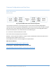
SCREW TERMINAL RS-485 PINOUT
PIN Name Description
1 T/R+
T
/R+ (Default 2
wire mode) R
X + (4 wire mode
input)
2 T/R- T/R- (Default 2 wire mode) RX- (4 wire mode input)
3
TD-
Transmit - (4 wire mode only) – Device output
4
TD+
Transmit+ (4 wire mode only) – Device output
5
Ground (GND)
Signal Ground
Fig 2. RS-485 Screw Terminal Pinout
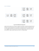
Fig 3. RS-485 Wireless Bridge Connectors and Pins