RS-485 Wireless Bridge USERS MANUAL R02
Contents Overview ....................................................................................................................................................... 3 Specifications ................................................................................................................................................ 3 Performance ............................................................................................................................................. 3 Power Requirements ...
Overview The RS-485 wireless bridge is designed to be a transparent RS-485 cable replacement. The RS-485 Wireless Bridge has a five pin screw terminal connector that can be configured for either RS-485 twowire or four-wire communications mode. The RS-485 Wireless Bridge is available in three different frequency and RF power options differing by frequency and RF output power options. It is possible to mix and match wireless bridge products.
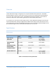
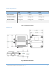
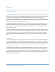
Power Requirements 24LP 24HP 09SX INPUT VOLTAGE 7-30VDC 7-30VDC 7-30VDC TRANSMIT CURRENT 12mA @ 12V 40mA @ 12V 270mA @ 12V RECEIVE CURRENT 12mA @ 12V 12mA @ 12V 17mA @ 12V Table 2. Power Requirements Mechanical Fig. 1 Mechanical Dimensions RS-485 WIRELESS BRIDGE USER’S MANAUL REV.
The mechanical dimensions for the wireless bridge are shown in Figure 1. The mechanical dimensions are shown with the optional DIN rail mount bracket which is not included with the standard part number. Mechanical data for the antenna is not shown. Pinout and Wiring The RS-485 Wireless Bridge uses RS-485 2-wire mode by default. In a normal 2-wire scenario only pin 1 (T/R+), pin 2(T/R-) and pin 5 (Signal GND) are used. The RS-485 Wireless Bridge can be set up to use 4wire mode.
Operation Standard Operation The RS-485 Wireless Bridge is designed to be data transparent. By default, any data sent into one device is broadcast and received by all other Wireless Bridge devices within range. Any device that receives the transmitted data packet will send the received data out the serial port to its host. Without any configuration the Wireless Bridge will operate in a point-to-point or point-to-multipoint mode making it easy to replace an RS-485 multi-drop cable.
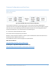
Common Configurations and Use Cases Radio Architectures Point-to Point Fig. 4 Typical RS-485 2-Wire Point-to-Point Configuration The most basic architecture is a 2-wire point-to-point. In this mode, one Wireless Bridge Device communicates with a second Wireless Bridge Device. If more than one pair of radios are within range of each other, then certain addressing commands should be set within the on board Digi XBee radio to isolate the individual pairs.
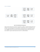
Point-to-Multipoint Fig. 5 Point-to-Multipoint Configuration Figure 5 shows a typical point-to-multipoint configuration. By default, all the Wireless Bridge devices will broadcast their data meaning that point-to-multipoint mode will work without any configuration. Used this way, the Wireless Bridges are connected to devices that typically work in a poll/response protocol such as MODBUS.
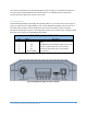
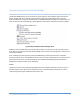
Communicating with the Wireless Bridge The Wireless Bridge device can be connected to a PC through the micro USB port. Figure 6 shows the device manager view of an example connected device. Note that a single device shows up as two separate COM ports. In Figure 6, the COM ports are COM43 & COM44. The COM port numbers will vary from machine to machine depending on what COM port device drivers have been previously installed. Fig.
Fig. 7 Data and Information Terminals RS-485 WIRELESS BRIDGE USER’S MANAUL REV.
RS-485 Command Reference Table Main command Function Command Name Displays list of main commands Displays device serial number help info set & get Default Value Value Range NA No parameters NA No parameters defaults Restores factory default settings. NA No parameters mode mode 2 = RS-485 2-wire mode 3 = RS=485 4-wire 2 2 or 3 Enables JSON output format when used with an ADIO Wireless Bridge when en = 1 0 0 or 1 NA No parameters 9600 1200 - 115200 0 0 or 1 pkts.en store uart.
Fig. 9 Terminal Session Command Example Configuring Two-wire or Four-Wire Mode The default setting for the RS-485 Wireless Bridge is two-wire mode. The communications mode is controlled by the uart.mode command. To change to four-wire mode set the uart.mode to 3. RS485> set uart.mode 3 Use the store command to write any changed parameters to non-volatile memory. Changing the Baud Rate The Wireless Bridge device is made up of two main components: 1. The host processor 2.
Example: Changing the baud rate from the default 9600 to 115200 bps. Step 1: Using the X-CTU program, the XBee radio module is discovered on the data port – in this case COM43. The baud rate is changed to 115200. The “Write” button is used to store the setting. Fig. 10 X-CTU Baud Rate Setting Step 2: On the Wireless Bridge information terminal (COM44 in this example) the set uart.rate 115200 is issued followed by set store. RS-485 WIRELESS BRIDGE USER’S MANAUL REV.
Fig. 11 Uart Rate Setting Example Configuring the XBee Module The RS-485 wireless bridge utilizes the Digi XBee module. Consequently, all radio settings can be read or set with Digi AT commands or Digi X-CTU software. As a general rule the only commands that might need be set are the Networking and Serial Interfacing commands. Any I/O commands or other features are not used. See Digi’s website at www.digi.com and the XBee user manual and discussion forums for more information.
Antennas The Wireless Bridge uses an RP-SMA Female connector. The Wireless Bridge is approved to be used with any 2.1dBi RP-SMA Male antennas that are frequency compatible. Datawave antenna part numbers include: Part Number: ANT-2400-RP-2-A (2.4 GHz for the 24LP & 24HP variants) Part Number: ANT-900-RP-2-A (900 MHz for the 09SX variant) Part Numbers and Compatibility The RS-485 Wireless Bridge comes with three basic options depending on range requirements. The 24LP and 24HP operate at 2.
Certifications United States (FCC) The Datawave Wireless Bridges comply with Part 15 of the FCC rules and regulations. Compliance with the labeling requirements, FCC notices and antenna usage guidelines is required. FCC notices IMPORTANT: The RF device has been certified for remote and base radio applications. This equipment has been tested and found to comply with the limits for a Class B digital device, pursuant to Part 15 of the FCC Rules.