Analog & Digital I/O Wireless Bridge USERS MANUAL R02
Contents Overview ....................................................................................................................................................... 3 Specifications ................................................................................................................................................ 3 Absolute Maximum Ratings ......................................................................................................................
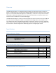
Overview The ADIO Wireless Bridge is a configurable Analog or Digital input and output wireless transmission device. It is designed to measure and replicate Analog or Digital I/O signals and wirelessly transmit those signals to a second ADIO Wireless Bridge device. Additionally, it can be used in conjunction with the RS232, RS-485 or USB Wireless Bridges to measure and transmit data back to a serial host device. In this mode it can act as a medium to be a wireless data logger.
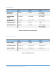
Performance 24LP 24HP 09SX OVER-THE-AIR DATA RATE 250 Kbps 250 Kbps Low: 10Kbps Mid: 110Kbps High: 250Kbps INDOOR/URBAN RANGE Up to 200ft. Up to 300ft. Up to 1000ft. OUTDOOR/ RF LINEOF-SITE RANGE Up to 4000ft. Up to 2 miles Up to 10 miles TRANSMIT POWER 6.3 mW 63 mW 1 Watt RECEIVE SENSITIVITY -101 dBm -101 dBm Low: -113 dBm Mid: -106 dBm High: -103 dBm Table 1.
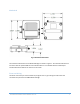
Mechanical Fig. 1 Mechanical Dimensions The mechanical dimensions for the Wireless Bridge are shown in Figure 1. The mechanical dimensions are shown with the optional DIN rail mount bracket which is not included with the standard part number. Mechanical data for the antenna is not shown. Pinout and Wiring The device uses a five pin screw terminal for I/O signals. Pin 5 is ground. Figures 2 & 3 show the connectors and pinout for the ADIO Wireless Bridge. ADIO WIRELESS BRIDGE USER’S MANAUL REV.
SCREW TERMINAL ADIO PINOUT PIN 1 2 3 4 5 Name Direction Channel 1 Channel 2 Channel 3 Channel 4 Ground (GND) Default Input Default Input Default Input Default Input Signal Ground Fig 2. Screw Terminal Pinout Fig 3. Wireless Bridge Connectors and Pins Operation Standard Operation The ADIO Wireless Bridge is intended to measure Analog or Digital Input data lines and wirelessly transmit those signal levels to a second ADIO Wireless Bridge to output the measured signal levels.
enumerate exactly the same, as a general rule the lower numbered COM port is for Wireless Bridge configuration. The higher numbered COM port can be used to transmit or receive data over the USB port. LED Indication The wireless bridge has four LEDS for indication. The Blue Power LED is lit any time the Wireless Bridge is properly powered. A green TX LED and yellow RX LEDs indicate activity on the serial port of the device.
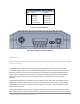
Communicating with the Wireless Bridge The Wireless Bridge device can be connected to a computer through the micro USB port. Figure 4 shows the device manager view of an example connected device. Note that a single device shows up as two separate COM ports. In Figure 6, the COM ports are COM43 & COM44. The COM port numbers will vary from machine to machine depending on what COM port device drivers have been previously installed. Fig.
Fig. 5 Data and Information Terminals ADIO WIRELESS BRIDGE USER’S MANAUL REV.
Common Configurations and Use Cases Analog Signal Bridge Fig. 6 Typical 4 Channel Analog input to Analog Output Signal Bridge A common configuration for the ADIO Wireless Bridge is as an Analog signal bridge. By default the ADIO Wireless Bridge is configured to accept 0-10V analog inputs. By configuring a second Wireless Bridge for Analog outputs the analog input voltages on the transmitting radio will appear at the outputs on the receiving radio. Not all channels need to be the same type.
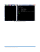
For the radio with Analog outputs: 1. 2. 3. 4. Set the channel type Set the channel token value to match the value of the input channel token. Set pkts.en parameter to 1. Optional: Use set store to save the configuration Example: Figure 7 shows a setup for two radios. COM44 is the information COM port of Radio A and COM57 is the information COM port of Radio B. In this example, Radio A is the input radio and Radio B is the output radio.
Digital Signal Bridge This is similar to the analog signal bridge except that the outputs will transition when the inputs cross logic voltage thresholds. The High input voltage threshold is 2.1V and the low threshold is 0.8V. By default the high output voltage is 3.3V but this can be adjusted with the chX.lvl.dovolts command. See the ADIO command reference table for details. For digital I/O line passing the following setup should occur. Optional parameters are noted. Input radio: 1. 2. 3. 4. 5. Set the ch.
Fig. 9 Example JSON Packet Output ADIO WIRELESS BRIDGE USER’S MANAUL REV.
ADIO Command Reference Table Main command Function Command Name help info sample set & get chX.lvl.dovolts ch.X.lvl.def ch.X.lvl.tmo ch.X.token ch.X.type ch.X.cd Default Value Value Range Displays list of main commands Displays device serial number NA NA No parameters No parameters Outputs sample inputs in mV to the information port NA No parameters 3300(3.
Main command Function Command Name io.txrate io.dataout io.name pkts.en Sets the sample and RF transmission rate. This command must be enabled for I/O line passing Sets the output data format to either text or JSON format. Text = 0, JSON = 1. Allows for a user settable string of up to 20 characters. Zeros are sent for all characters that are not set Enables JSON output format when used with an ADIO Wireless Bridge when en = 1 Stores settings to non-volatile memory. store uart.
Changing the Baud Rate The Wireless Bridge device is made up of two main components: 1. The host processor 2. XBee radio module The host processor manages the USB interface, the information menu and communication to and from the XBee radio module. Changing the device’s baud rate is a two-step process. In order to change the baud rate successfully, the following steps must be followed in order. 1. Change the baud rate on the XBee module through the data COM port using AT commands or the X-CTU program.
Step 2: On the Wireless Bridge information terminal (COM44 in this example) the set uart.rate 115200 is issued followed by set store. Fig. 12 Uart Rate Setting Example Configuring the XBee Module The ADIO wireless bridge utilizes the Digi XBee module. Consequently, all radio settings can be read or set with Digi AT commands or Digi X-CTU software. As a general rule the only commands that might need be set are the Networking and Serial Interfacing commands. Any I/O commands or other features are not used.
Antennas The Wireless Bridge uses an RP-SMA Female connector. The Wireless Bridge is approved to be used with any 2.1dBi RP-SMA Male antennas that are frequency compatible. Datawave antenna part numbers include: Part Number: ANT-2400-RP-2-A (2.4 GHz for the 24LP & 24HP variants) Part Number: ANT-900-RP-2-A (900 MHz for the 09SX variant) Part Numbers and Compatibility The RS-485 Wireless Bridge comes with three basic options depending on range requirements. The 24LP and 24HP operate at 2.
Certifications United States (FCC) The Datawave Wireless Bridges comply with Part 15 of the FCC rules and regulations. Compliance with the labeling requirements, FCC notices and antenna usage guidelines is required. FCC notices IMPORTANT: The RF device has been certified for remote and base radio applications. This equipment has been tested and found to comply with the limits for a Class B digital device, pursuant to Part 15 of the FCC Rules.