Visualize · Mobilize · Realize MCL-Collection 123 Print v1.1x User Manual Visualize…printers with intelligence www.mcl-collection.
i. Preface Background Copyright statement 123 Print is developed by MCL Technologies to bring intelligence to Datamax printers. © 2007 MCL Technologies 123 Print v1.1x User Manual DATAMAX is a registered trademark of Datamax Bar Code Products Corporation. Seagull and BarTender are trademarks or registered trademarks of Seagull Scientific, Inc.
1. Primer........................................................................................................................ 5 1.1. What is 123 Print......................................................................................................... 6 1.2. Sample Labels............................................................................................................. 7 1.3. Project Flow................................................................................................
Appendix A – Sample License Certificate ................................................................................. 218 Appendix B – Datamax Printer Setup...................................................................................... 220 Appendix C – Supported Datamax Printers .............................................................................. 221 Appendix D – System Requirements.......................................................................................
Chapter 1 : Primer 1. Primer Overview Document introduction This document is a User Guide for 123 Print V1.x. It is divided into several chapters to give you a thorough understanding of the use of 123 Print. Chapter 1 – Primer Chapter 2 – Getting Started Chapter 3 – Creating a Project Chapter 4 – Designing a Label Chapter 5 – Using Processes Chapter 6 – Simulating Your Project Chapter 7 – Deploying a Printer Project Accompanying appendices provide supplementary information.
Chapter 1 : Primer 1.1. What is 123 Print General introduction 123 Print This section gives an overview of 123 Print, its purpose and its benefits. 123 Print is a design environment to create simple, stand-alone applications that run on Datamax printers.
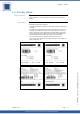
Chapter 1 : Primer 1.2. Sample Labels General introduction Sample labels This section shows some sample labels to give you an idea of the kinds of labels you can print using 123 Print projects on Datamax printers. The sample labels shown here were designed using Seagull’s BarTender label creation software. 123 Print provides the capability to associate and print variable data on labels. Consider the sample labels shown below.
www.mcl-collection.
Chapter 1 : Primer 1.3. Project Flow General introduction 123 Print structures your project flow using a combination of screens and processes that you create via 123 Print’s User Interface and Labels. This section gives a high level view of the flow and interrelationship between the screens that are created via the User Interface and those created via Labels. With User Interface, you can print any static label you want.
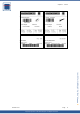
Chapter 1 : Primer Select Label:004 Pallet Label ▼▲ 2 In this case, the third screen will look like the screen below. Notice that the label name, Pallet Label, from screen (2) has automatically been displayed on the first line of screen (3). Pallet Label Qty to Print:1.. 3 ▼▲ The user presses the Fwd ↑ and Rev ↓ buttons on the printer’s front panel to increment or decrement the quantity of the label to be printed.
Chapter 1 : Primer User Interface: Core screen flow Select Label:003 Item Label Labels: Label program ▼▲ 2 C Enter Item Code _____________ Item Code A D Process: Get Item Description from Lookup File Item Description X Item on Scale? Y/N _ B E Process: Weigh Item Map variables into label format Item Label Qty to Print:1..
Chapter 2 : Getting Started 2. Getting Started Overview Chapter 2 introduction This chapter covers the following topics: Topic Page 2.1. Installation 13 2.2 Activation 17 2.3 General Setup 2.3.1 2.3.2 2.3.3 2.3.4 25 DPL Connection MCL Connection Local Settings Others www.mcl-collection.com Topics This chapter describes the installation and setup of 123 Print.
Chapter 2 : Getting Started 2.1. Installation General introduction Installation This section describes how to install 123 Print. 1 Double-click on the 123 Print installation executable which you have downloaded. The default folder in which 123 Print is installed is C:\123Print A welcome screen is displayed as shown below Click Next to proceed with the installation www.mcl-collection.
Chapter 2 : Getting Started An end-user license agreement is displayed as shown below To accept the license terms and proceed 3 Click Yes 4 5 6 www.mcl-collection.com As shown below, a screen is displayed prompting you to enter the location where you want to install 123 Print.
Chapter 2 : Getting Started As shown below, a screen is displayed to show you the progress of the installation 7 www.mcl-collection.
Chapter 2 : Getting Started Starting 123 Print Once 123 Print is installed, start it by: Double click on the 123 Print shortcut icon on the Windows desktop 1 www.mcl-collection.
Chapter 2 : Getting Started 2.2. Activation General introduction This section describes the activation process for 123 Print. During the activation process you will be prompted to choose between a Software Activation and a Hardware Activation for your 123 Print license. Be sure to understand the benefits of each method and the consequences of choosing one method over the other. Be sure to make your choice carefully. The activation method you choose cannot be changed at a later stage.
Chapter 2 : Getting Started Enter the License Number found on your License Certificate 4 Click Next October 2007 Copyright © 2007 • MCL Technologies • All Rights Reserved www.mcl-collection.
Chapter 2 : Getting Started End-user license agreement MCL’s End-User License Agreement is displayed as shown below. Before proceeding, you must read and accept these license terms. 5 6 7 Read and scroll down to the bottom of the terms Check the checkbox to accept the license terms Click Next 8 9 www.mcl-collection.
Chapter 2 : Getting Started Software versus hardware activation The next step is to choose between Software Activation and Hardware Activation. This choice is very important as it cannot be changed at a later stage. Software Activation: Using this method of activation, 123 Print computes a Serial Number from various components on your PC. 123 Print then ties your license number to this computed Serial Number. Thus, your software becomes PC Dependent.
Chapter 2 : Getting Started 12 Click Next to confirm and proceed Indicate if you want to use on-line or off-line activation 13 Click the appropriate radio button 14 Click Next Your system needs internet access for on-line activation to be possible. This example uses on-line activation. Consequently, the On-Line Activation screen is displayed as shown below. The off-line activation mode will step you through the activation process in a similar fashion.
Chapter 2 : Getting Started 15 Enter the Password found on your License Certificate 16 Click Next www.mcl-collection.com You are prompted to confirm that your registration information is accurate 17 Click Next to confirm the details you entered on the previous screens. 123 Print now connects to MCL’s Licensing Server and records your details on the server. The Licensing Server then returns an Activation Key. When the Activation Key is received, your software is ready to be used.
Chapter 2 : Getting Started 18 Print this information and keep it in a safe place for later use in case of disaster recovery. 19 Click Next to validate your activation. 20 Edit the entry or browse to the location where you want your License Key backed up 21 Click Next Note: It is very important for you to record and save a backup of your license key. This is the only way MCL Technologies can help you recover your 123 Print license in the event of a disaster.
Chapter 2 : Getting Started A successful backup screen is displayed as shown here. 22 Click Finish Starting 123 Print When the activation is completed, 123 Print is started automatically. To start 123 Print again in the future, double click on the 123 Print short cut on the Windows desktop www.mcl-collection.
Chapter 2 : Getting Started 2.3. General Setup General introduction Setup This section describes the setup of 123 Print to allow it to operate in your environment. This setup involves the settings that are required by 123 Print to work with your printer, simulate your project, and integrate with BarTender.
Chapter 2 : Getting Started 2.3.1. DPL Connection DPL Connection Setup your printer interface for DPL Mode communications. In the Setup dialogue box: 1 Click on the DPL Connection tab If you want to use network communications for your DPL commands: 2 Edit the Printer TCP port with the appropriate port number (typically 9100 or 3000). If you want to use serial communications for your DPL commands: 3 Edit the Serial settings with values appropriate for your printer www.mcl-collection.
Chapter 2 : Getting Started 2.3.2. MCL Connection MCL Connection Next setup your printer interface for MCL Mode communications. In the Setup dialogue box: 1 Click on the MCL Connection tab The MCL Connection options screen is displayed as shown here MCL Group ID can be any number from 001 to 255. In the MCL Group ID setting, enter the value of the Group ID you assigned to the printer to which you want to connect.
Chapter 2 : Getting Started 2.3.3. Local Settings Local Settings Next, setup project simulation options. In the Setup dialogue box: Click on the Local Settings tab 1 The Local Settings screen is displayed as shown here The project you run on a printer may require inputs from peripherals such as a barcode scanner on printer port 1 and weight scale on printer port 2.
Chapter 2 : Getting Started Assign Com 2 Printer Port To This option is identical to the Assign Com 1 option. This option simply lets you simulate a peripheral, such as a weight scale, that would normally be connected to port 2 on the printer. 3 Select the desired option for printer port 2 simulation Assign Internal Printer Port To This option allows you to simulate label printing when you are running your project in simulation.
Chapter 2 : Getting Started 2.3.4. Others Others Set up the values for 123 Print’s integration with BarTender or DPL labels. In the Setup window: 1 Click the Others tab The Others dialogue box is displayed as shown here If BarTender is installed and activated on your system: 2 In the Printer Name field, identify the default printer to be used for your project.
Chapter 2 : Getting Started Timer is used to set the duration, in seconds, of the display of the Welcome screen. The Welcome screen is typically displayed momentarily only Edit the timer value, or 6 Use the up and down arrows beside the timer field to increment or decrement the value of the field. www.mcl-collection.
Chapter 3 : Creating a Project 3. Creating a Project Overview Chapter 3 introduction Description This chapter describes how to use 123 Print to create projects and label programs for your Datamax printers. 123 Print provides you with all the tools necessary to create applications for your Datamax printer.
Chapter 3 : Creating a Project 3.1. Project Description General introduction New Project This section describes how to begin creating your 123 Print project. Start first by creating a new project. On the menu bar: Click File Click New 1 2 Alternatively, on the tool bar, click on the New Project icon. The Project Description screen is displayed as shown here Project Name * The name you wish to assign to your project/application Version * The build version of your application.
Chapter 3 : Creating a Project On the Project Description screen: 3 Edit the fields with the appropriate data www.mcl-collection.com When you have completed editing these fields, notice that the following buttons appear on the left-hand side of the main window: The functions associated with these buttons are discussed in the subsequent sections of this chapter. These are the functions used to create your 123 Print project.
Chapter 3 : Creating a Project 3.2. User Interface General introduction This section describes the User Interface core screens of your 123 Print project. The User Interface is where you configure the core screens with which the user will interact on the Datamax printer. User Interface Click the User Interface button on the lefthand side of the main window, or on the menu bar: 1 Click Project 2 Click User Interface The User Interface window is displayed.
Chapter 3 : Creating a Project Text Display The User Interface for a large graphical display printer is as shown here. www.mcl-collection.
Chapter 3 : Creating a Project Graphical Display Small The User Interface for a small graphical display printer is as shown here: Graphical Display Status Toolbar The status toolbar across the top of the graphical display screens gives the following printer status: Printer is Ready Printer is Paused Printer is Printing The Printer is Printing status is accompanied by the Printer Ready status and a Printing Progress indicator as shown here: October 2007
Chapter 3 : Creating a Project 3.2.1. Welcome Screen Welcome Screen The Welcome screen is the first screen the user will see when they start your 123 Print project on the printer. You can edit the welcome you want to give the user. Notice that, by default, 123 Print uses the details you entered in the Project Description in Section 3.1.
Chapter 3 : Creating a Project As you make your changes, the result will appear in the display in the top-half of the editing window. next to the Welcome screen in the top-half of the editing The clock window sets the delay period for this screen. By default, this delay is set to 2 seconds. This means that when the project is run on the printer, the printer will pause for 2 seconds on the Welcome screen before moving on to the Select Label screen.
Chapter 3 : Creating a Project The Footer Soft Keys show the function of the Datamax printer keys in an MCL application. These may be defined on a project-by-project basis as described is Section 3.5.1 - Soft Keys Setup – Graphical Display Only. The two lines of the main graphical display show the same information as that shown on the two lines of a text display screen for the equivalent screen.
Chapter 3 : Creating a Project Below shows an example of a Welcome screen edited to have an image and fixed text on Line 2: control allows you to edit As with the text display screen, the clock the Welcome screen delay: 12 Edit the value of the delay from 0 - 99 seconds, or 13 Increment or decrement the value of the delay using the up and down arrows beside the delay entry field.
Chapter 3 : Creating a Project 3.2.2. Select Label Screen Select Label screen The Select Label screen is displayed after the Welcome screen has been displayed. You may edit this screen to give the user different prompts than those supplied by default by 123 Print. To edit the Select Label screen, on the User Interface window: Click on the Select Label screen, or 1 2 Click the Select button at the bottom of the window As with the Welcome Screen (Section 3.2.
Chapter 3 : Creating a Project 4 On Line 2 choose the method you want to use to select the label The Datamax printer cannot accept input from both a connected keyboard and a barcode scanner for a given input field. However, it can accept input from the front panel and a connected keyboard, or from the front panel and a barcode scanner, or from just the front panel.
Chapter 3 : Creating a Project 4 5 6 7 8 Select a Header option Edit the User Prompt box to display the desired prompt On Select Label choose the method you want to use to select the label. These options are the same as those described above for Select Label - Text Displays.
Chapter 3 : Creating a Project 3.2.3. Quantity to Print Screen Quantity to Print screen To edit the Quantity to Print screen, on the User Interface window: Click on the Quantity to Print screen, or 1 2 Click the Quantity button at the bottom of the window As with the Welcome Screen (Section 3.2.1 – Welcome Screen), the Quantity to Print Screen varies according to the display type available on the printer model selected for the given project.
Chapter 3 : Creating a Project the front panel and a barcode scanner, or from just the front panel. 4 Graphical Display Large If you choose Qty Using Front Panel, the user must use the Fwd ↑ and Rev ↓ buttons on the front panel to increment or decrement the quantity. If you choose Qty Using Keyboard, keyboard and front panel input is enabled; the user may input a quantity from the keyboard or use the Fwd ↑ and Rev ↓ buttons on the front panel to increment or decrement the quantity.
Chapter 3 : Creating a Project 4 5 6 7 8 Select a Header option Edit the User Prompt box to display the desired prompt On Select Quantity choose the method you want to use to input the quantity. These options are the same as those described above for Quantity to Print - Text Displays.
Chapter 3 : Creating a Project 3.2.4. Print Error Message Screen Print Error Message screen The Print Error Message Screen is displayed by the Datamax printer whenever it detects a print error. You can display whatever message is appropriate here for your environment. To edit the Print Error Message screen, on the User Interface window: 1 Click on the Print Error Message screen, or 2 Click the Error button at the bottom of the window As with the Welcome Screen (Section 3.2.
Chapter 3 : Creating a Project Message screen The Print Error Message Screen editing window for a large graphical display printer is as shown here: Notice that this screen has the same display screen editing options — a Header, Footer and two lines on the main display — as those described in Section 3.2.1 – Graphical Display Elements.
www.mcl-collection.
Chapter 3 : Creating a Project 3.3.
Chapter 3 : Creating a Project To associate a label with your 123 Print project, 4 Click the button at the bottom of the Labels List window Each time you add a label, 123 Print assigns a sequence number to the label. This system assigned number is displayed in the Labels List window in the left most column called #. This number determines the sequence order in which the labels are displayed on the Select Label Screen (see Section 3.2.2 – Select Label Screen).
Chapter 3 : Creating a Project Label template for dynamic label If you are simply associating a static label, you are done using the Labels function for this label 6 Click OK to close the Labels Properties and return to the Labels List window to add other labels as necessary Once you have added a label, in this case the label LocationMCL2.
Chapter 3 : Creating a Project 3.3.1. Edit General Introduction If you have Seagull Scientific’s BarTender installed and activated on your system, and are working with a BarTender *.btw file, when you press Edit, 123 Print starts Bartender with your active label open for editing. If you do not have a BarTender label and are working directly with a *.txt or *.dpl file, Edit will display the DPL code of the label for editing. Edit 1 Click the Edit button to view and edit your selected label.
Chapter 3 : Creating a Project 3.3.2. Variables General introduction Variables is one of the main functions in 123 Print to enable you to create labels that are printed with dynamic content. Consider the labels shown in Section 1.2 – Sample Labels. These labels include variable data such as the date and time at the moment the label was printed. This function allows you to include this kind of variable information on your labels.
Chapter 3 : Creating a Project Graphical Display Large The 123Print Designer window for a large graphical display printer is as shown here. Only one prompt screen is displayed at a time for large graphical displays. Use the scroll bar provided to navigate through your prompt screens. Graphical Display Small The 123Print Designer window for a small graphical display printer is as shown here. Up to 2 prompt screens are displayed at a time for small graphical displays. www.mcl-collection.
Chapter 3 : Creating a Project Creating a label program To show you how to design a label program, an example is used extensively herein. This example creates Warehouse Shelving labels, like the one shown below, for a self-service warehouse. The user would print labels like this to indicate the location for all the products in the warehouse. The labels would then be applied to the shelving racks in the warehouse to assist customers in finding the product they want to purchase.
Chapter 3 : Creating a Project Input Methods When you enter a prompt, you must select an Input Method for the prompt. This determines how the user will be able to enter data on the given screen. The Input Methods are entered on Line 2 of a screen prompt.
Chapter 3 : Creating a Project The Warehouse Shelving example only requires two of the input properties to be setup: Result Variable Force Uppercase The Result Variable is the variable where the user’s input will be saved when they enter a location on the screen prompt. The Force Uppercase will prevent the user from entering lowercase letters when they enter a location on the screen prompt.
Chapter 3 : Creating a Project Various kinds of Variables may be used in a 123 Print label program. To work with the variables, select one of tabs: User Local All Local Global System You cannot write to a System Variable. Therefore, these are not applicable for use as a resultant variable and are grayed out whenever you are creating a resultant variable. Please see Section 5.1 – Introduction to 123 Print Variables for more detailed information about variables.
Chapter 3 : Creating a Project Notice that the Result Variable field has now been filled with the name of the Variable you just created: [A0] Location. You have now completed the first prompt screen of your label program. For this Warehouse Shelving example, repeat the above steps to create a second prompt screen— Enter Product Name:. Create a Resultant Variable [A1] Product_Name as the storage location for the user input for this screen prompt.
Chapter 3 : Creating a Project Continuing with the Warehouse Shelving example, create a screen that allows the user to confirm that the product name they entered is correct. 8 Select Screen 3 on the left-hand side of the 123Print Designer window. Then proceed as for Screen 1 and 2, by first entering the text to be displayed on Line 1, and then the action to be performed on Line 2. 9 Type Product Name: on Line 1 10 For Line 2 select the Display Data option.
Chapter 3 : Creating a Project 12 Click on the User Local tab 13 Select the Variable [A1] Product_Name. 14 Click OK In order for the user to be able to see this screen and read the displayed data, you must display the screen long enough for the user to be able to read it. To do so, set the Display Time option. This will display the screen momentarily only—for the period you set (in seconds). 15 Set the Display Time to 2 seconds When completed, the properties for Screen 3 are as shown above. www.
Chapter 3 : Creating a Project www.mcl-collection.
Chapter 3 : Creating a Project Processes In the Warehouse Shelving example, you will want to perform different operations depending upon the input the user gives to the confirmation prompt. If the user enters Yes to confirm that the Product Name is correct, you want to proceed to print the label. If the user enters No to indicate that the Product Name is incorrect, you will want to return to the product name prompt screen to give the user an opportunity to enter the Product Name again.
Chapter 3 : Creating a Project 21 Select the Test and Branch process A Conditional Branching dialogue box is displayed as shown here Using this process, one action will be performed if Yes has been entered on screen 4. Otherwise, a different action will be performed. This is referred to as Conditional Branching. www.mcl-collection.com The first thing to do is to choose the Variable on which the test is to be performed.
Chapter 3 : Creating a Project 25 Set the Then Goto field to Continue 26 Set the Else Goto to [S_02] (Screen 2). The final Conditional Branching process entries for this example are as shown here 27 Click OK www.mcl-collection.com The process setup is completed. The 123Print Designer window is displayed again, as shown below, with an entry for the Test & Branch process you just defined.
Chapter 3 : Creating a Project 3.3.2.1. Front Panel Up/Dw Numeric General introduction As discussed in Section 3.3.2 – Variables, Input Methods, several input methods are available for your screen prompts. This section discusses the Front Panel Up/Dw Numeric input method and the properties you need to set up when you select this input type. Front Panel Up/Down Numeric allows the User to input a number within the range specified (e.g. 1-100).
Chapter 3 : Creating a Project 3.3.2.2. External Keyboard General introduction As discussed in Section 3.3.2 – Variables, Input Methods, several input methods are available for your screen prompts. This section discusses the External Keyboard input method and the properties you need to set up when you select this input type. External Keyboard allows the User to use an external keyboard for inputs to the label program screen prompts. Input Type Set the type of input that should be accepted (e.g.
Chapter 3 : Creating a Project Extract To Set the ending position if extracting only certain characters from the input For example, if you set Extract From 4 and Extract To 6, you will extract “555” out of 0005550 Force Uppercase input. Users will not be able to enter lower case letters into a screen prompt if this option is selected Default Value Type a value or set a default value using the contents of a variable.
Chapter 3 : Creating a Project 3.3.2.3. External Barcode Reader General introduction As discussed in Section 3.3.2 – Variables, Input Methods, several input methods are available for your screen prompts. This section discusses the External Barcode Reader input method and the properties you need to set up when you select this input type. External Barcode allows the User to use an external barcode scanner for inputs to the label program.
Chapter 3 : Creating a Project Type a value or set a default value using the contents of a variable. If you use a variable, remember to assign a value to the variable someplace in your label program Result Value Select the variable in which the user input should be stored Output Format Set the format you want to use when saving the input from the external barcode reader. Several options are available such as fill blank on left, fill zeros on left. Select the appropriate format for your program design.
Chapter 3 : Creating a Project 3.3.2.4. Weight Scale General introduction As discussed in Section 3.3.2 – Variables, Input Methods, several input methods are available for your screen prompts. This section discusses the Weight Scale input method and the properties you need to set up when you select this input type. Weight Scale allows the user to connect and use a weight scale to give inputs to the label program running on the printer.
Chapter 3 : Creating a Project Start with End With Extract from Received Data From Position To Position This function is automatically active and cannot be unchecked. This allows your printer to receive and interpret the data from the weight scale. The following options allow you to indicate to your label program the format of the data coming from the weight scale. Check your weight scale manual for message formatting details.
Chapter 3 : Creating a Project Following is an example to illustrate the use of some of the options described above. If the request to ask your scale to send weight information has the following structure: as a start of text character, followed by the command SP64, and ending with a (Carriage Return, Line Feed), then your Data To Send settings should look as shown below: www.mcl-collection.
Chapter 3 : Creating a Project The remaining weight data may be further refined by selecting an output format, such as stripping leading zeros. The result may then be saved in a variable for additional processing or printing. www.mcl-collection.com Below shows what the complete Input Method properties might be for a Weight Scale input.
Chapter 3 : Creating a Project 3.3.2.5. Select Value from List General introduction As discussed in Section 3.3.2 – Variables, Input Methods, several input methods are available for your screen prompts. This section discusses the Select Value from List input method and the properties you need to set up when you select this input type. Select Value From List allows the User to select the input value from a predefined list of values or from existing variables.
www.mcl-collection.
Chapter 3 : Creating a Project 3.3.2.6. Select Value from File General introduction As discussed in Section 3.3.2 – Variables, Input Methods, several input methods are available for your screen prompts. This section discusses the Select Value from File input method and the properties you need to set up when you select this input type. Select Value From File allows the user to select the input from a predefined lookup file (please reference Section 3.4 – Lookup Files).
Chapter 3 : Creating a Project Example Following is an example to illustrate the use of some of the options described above. This example involves a product file (Product.dat) with 4 fields per record. The first field in each record is a Product Code. If in the Select Record Using Field you select the Product Code, then this is the field that is used for browsing and searching.
Chapter 3 : Creating a Project 3.3.2.7. Display Data General introduction As discussed in Section 3.3.2 – Variables, Input Methods, several input methods are available for your screen prompts. This section discusses the Display Data input method and the properties you need to set up when you select this input type. Display Data allows the user to view the data stored in a variable. Display Value Type a value or set a value using the contents of a variable.
Chapter 3 : Creating a Project 3.3.3. Mapping General introduction Mapping is the function in 123 Print that allows you to convert a static label or label template into a dynamic label. Firstly, you require a static label that has the layout you want for the dynamic label. Next, you must associate this label with your 123 Print project as described in Section 3.3 – Labels. Then, using the static label as a template, map the variable data to the elements on the static label.
Chapter 3 : Creating a Project In the Mapping window, you will see the various elements (text fields, barcodes, etc) of the given label. If you have BarTender installed and activated on your system and are using a BarTender label, you will see a thumbnail of your label on the left of the Mapping window. The Mapping window gives you the following details about your label: Type of label element is indicated by a variety of icons that are displayed if BarTender is installed and you are working with *.
Chapter 3 : Creating a Project Returning to the Warehouse Shelving example started in Section 3.3.2 Variables, the following describes how the LocationMCL2.btw label would be mapped using the variables created in the example. 2 Double-click on the Replace By field for the first entry in the Mapping table – this element is the first of the two Barcodes on the example label The Variables list is displayed as shown here 3 4 Select the Location variable ( [A0] Location ) Click OK 5 www.mcl-collection.
Chapter 3 : Creating a Project Again the Variables list is displayed. Select the variable to be associated with this text field. When the label is printed, the contents of that variable will be printed as text where the text “location” was printed beneath the barcode on the static label. 6 Repeat the above steps for the remaining elements of the label. Select an element and assign a variable to it.
Chapter 3 : Creating a Project Result Labels The static LocationMCL2.btw label used in this Warehouse Shelving example looks as follows: When you run the label program you created for the Warehouse Shelving example, your screen prompts will request Location and Product Name for a given product. If you input a location of A78 – 25Z and a product name of OAK BOOKCASE, then the variables you created will contain the following: [A0] Location = A78 – 25Z [A1] Product_Name = OAK BOOKCASE 8 www.
Chapter 3 : Creating a Project Labels List When you return to the Labels List window, an entry will have been added for your label. Notice that several buttons are now active across the bottom of the window. These represent actions you can perform on the label. Right click on the label entry to get a more exhaustive list of the possible label actions—Add, Properties, Delete, Insert, Duplicate, Generate DPL File, Move Up and Move Down. Select the desired action.
Chapter 3 : Creating a Project Adding more labels To add a new label, simply click on the button. If you wish to add a new label and have it appear before the existing button. label in your Labels List, you should use the If you wish to duplicate your existing labels, including the screens associated with it – so as to only need to make minor modifications for the second label rather than having to start from nothing – you can simply right-click on the existing label and choose duplicate.
Chapter 3 : Creating a Project 3.4. Lookup Files General introduction 123 Print allows you to use lookup files in your printer project. Using printer inputs, such as a weight scale, and a lookup file you could print, for example, labels that include a product code, product description, product weight, and a date stamp. This section describes how to create Lookup files for your 123 Print projects.
Chapter 3 : Creating a Project Lookup File Data To review and edit the data in the Lookup file at any time, on the main Lookup Files window: 1 2 Delete Lookup File Click on the Data button Edit the data. See Section 3.4.4 – Edit Lookup File Data for details To delete a Lookup File from your project, Select the file you want to delete 1 2 Click on the Delete button You are prompted to confirm the request to delete a Lookup File.
Chapter 3 : Creating a Project 3.4.1. Add Lookup File Add Lookup file When adding a Lookup File, you can either create a lookup file from scratch or import data from another data source to create the lookup file. The file you create is of type *.dat. If you used the default paths when installing 123 Print, your lookup files are saved in: C:\123Print\Projects\.
Chapter 3 : Creating a Project 2 Give this lookup file a name, for example, Product Description The next lookup file property is the Memory property. The lookup file may be saved in flash, RAM, or optional flash memory on your Datamax printer when you download your 123 Print project and lookup files into your Datamax printer. 3 www.mcl-collection.com If you select , the lookup file is stored wherever the MCLClient is stored. This is typically in Flash memory.
Chapter 3 : Creating a Project As shown below, you can leave the data in the lookup file unsorted, or you can sort it using the first field or the first and second fields of the file records. The lookup file will be sorted and saved according to this sort selection. 4 Select the desired sort field(s), if any. 5 www.mcl-collection.com The next file property is the Separator property. 123 Print provides a variety of separators that can be used as field delimiters in the lookup file you are creating.
Chapter 3 : Creating a Project Add Lookup File from Import To see how to put data in the Lookup File you have created, please see Section 3.4.3 – Add Lookup File from Scratch To create your lookup file from an existing data source, Complete the Lookup File Properties as described above. 1 2 Click on the Import button in the Lookup File Properties www.mcl-collection.com Add Lookup File from Scratch To see how to create your Lookup File with data from an existing data source, please see Section 3.4.
Chapter 3 : Creating a Project 3.4.2. Add Lookup File from Import File Add Lookup File from import file In 123 Print, you can create a Lookup File from an existing data source. Several file types are valid for import: *.dat, *.txt, *.xls, *.cvs First, complete the Lookup File Properties as described in Section 3.4 – Add Lookup File. 1 Click on the Import button www.mcl-collection.
Chapter 3 : Creating a Project To select the file to be imported, 2 Enter a path and filename, or 3 Click on the browse icon If you click browse, an Add a Lookup File browse window is displayed as shown here 4 5 6 Select the appropriate file type of the file to be imported Navigate to the file you want to use Click Open www.mcl-collection.com The file you select appears in the Select a file – Import structure & data screen as shown here If you are importing a *.dat, *.txt., or *.
Chapter 3 : Creating a Project If you are importing a file, such as an excel file, in which the first row of your spreadsheet contains column headers that you want to use as field descriptors in your lookup file: 8 Check the checkbox beside First line = Column Title To preview the structure and data of the lookup file you are creating from the file being imported: 9 Indicate how many lines you want to view by editing the value beside Number of Lines, or use the arrows to increment or decrement the value in
Chapter 3 : Creating a Project The lookup will be created using the properties given here, using these field names, field lengths, field separators, etc. Any of the properties such as the field names or field length may be edited at this time.
Chapter 3 : Creating a Project The Lookup Files window is displayed with an entry for the Product Description lookup file being created. You have now created a Lookup File from a data source. The resulting Product Description.dat file for this example looks like this: 1234567890123|DMX 2345678901234|DMX 3456789012345|DMX 4567890123456|DMX A-4212 I-4212 M-4208 A-4210 |Datamax |Datamax |Datamax |Datamax You are prompted to confirm 16 Click Yes The revised Product Description.
Chapter 3 : Creating a Project 3.4.3. Add Lookup File from Scratch Add Lookup File from scratch In 123 Print, you can create a Lookup File from Scratch. First, complete the Lookup File Properties as described in Section 3.4 – Add Lookup File. 123 Print assigns the next available file code to this new file. Now create the structure for your lookup file Enter field names for the data in the Lookup File you are creating Enter the field lengths for the fields you created in step 1 1 2 3 www.
Chapter 3 : Creating a Project The main Lookup Files window is displayed as shown here Next, add your data to the Lookup File. In the Lookup Files window, Click the Data 5 Double click on the first field in the first row to edit it with the desired data Press or to move to the next field for editing. 6 button When all fields of a record have been filled in, or automatically advances you to the beginning of the next record.
Chapter 3 : Creating a Project Continue adding records until your Lookup File is completed Save Lookup File To save the Lookup File, Click OK 7 You are prompted to confirm that you want to save the file 8 Click Yes www.mcl-collection.com The Lookup File is closed with an updated file date and file size.
www.mcl-collection.
Chapter 3 : Creating a Project 3.4.4. Edit Lookup File Data General introduction Once a Lookup file is created from scratch or through importation of an existing data source, you can edit your Lookup File data. You may perform the following on your data records: Add Insert Modify Delete Edit Data The Lookup File data may be edited at any time—when the file is first being created or at a later time whenever changes are required.
Chapter 3 : Creating a Project Display / Hide columns You can hide any of the columns you do not want to see: 3 Right click any of the column headers A list of the columns is shown. A check mark beside a column indicates it is being displayed. No check mark indicates the column is hidden. To hide a column: 4 Select the column name of column(s) you want to hide www.mcl-collection.com This is a toggle function.
Chapter 3 : Creating a Project Add record To add a record: 1 Click the Add button A blank record is added to the file. 2 Enter the desired data for this record, for example the product information for Seagull’s BarTender software When all the data for the new record has been entered, 3 Press www.mcl-collection.com If your Lookup File is being sorted on Field 1, the record you added will automatically be sorted into the correct position in your file, as show here.
Chapter 3 : Creating a Project Insert a record To insert a record, Click on the record below the desired insertion point 1 2 Click the Insert button A record is added above the selected record. Enter the desired data for this record, for example the product information for Seagull’s BarTender License Server 3 www.mcl-collection.com Insertion at a desired point is only useful if you are inserting records in an unsorted file.
Chapter 3 : Creating a Project Modify a record To modify a record, 1 Click on the record to be modified 2 3 Change record order Click the Modify button Edit the data as desired. In this example, the product code for the inserted record is modified The arrows in the lower right-hand corner of the Lookup File – Data window allow you to change the order of the records in the Lookup File.
www.mcl-collection.
Chapter 3 : Creating a Project 3.5. System Setup General introduction This section describes the settings for your 123 Print project. Different settings are possible according to your printer display type. To enter System Setup, you must first have a project open.
Chapter 3 : Creating a Project Select the desired Date Format for your project Select the desired Time Format for your project Select the desired Font Code Page for your project www.mcl-collection.
Chapter 3 : Creating a Project 3.5.1. Soft Keys Setup – Graphical Display Only General introduction This section describes the Soft Key setup for your graphical display 123 Print projects. As described in Section 3.2 – User Interface, a 123 Print graphical display printer project provides a Footer option to display the function of the Datamax printer keys. 123 Print allows you to define the function of these keys on a projectby-project basis, thus making them Soft Keys.
Chapter 3 : Creating a Project The Soft Keys screen is displayed as shown here: Next decide whether you want text or an image to be displayed in the footer to show the functions you have applied to the keys. October 2007 Copyright © 2007 • MCL Technologies • All Rights Reserved Page 113 www.mcl-collection.com The keys found on your Datamax printer are depicted with a Key Code box beneath each key.
Chapter 3 : Creating a Project 6 Select the Text or Image radio button If you select Text, simply edit the text box provided for each key to reflect the given function of the key, as shown here: www.mcl-collection.
Chapter 3 : Creating a Project Graphical Display – Large Screen The Soft Key footer image for a large screen graphical display should be a monochrome *.bmp image with the following specifications: Black and white 1 bit Uncompressed Max 240x320 px Graphical Display – Small Screen The Soft Key footer image for a small screen graphical display should be a monochrome *.
Chapter 3 : Creating a Project 3.5.2. Auxiliary Communications General introduction Setup This section describes the auxiliary communications settings in order for your 123 Print project to be able to communication with peripherals connected serially to your Datamax printer. To enter auxiliary communications setup, you must first have a project open.
Chapter 3 : Creating a Project Com 2 (if installed on your Datamax printer) is typically used to support non-barcode scanning peripherals such as weight scales. Any serial device may be connected here. 5 Select Com 2 port settings to match those of your peripheral device www.mcl-collection.
Chapter 3 : Creating a Project The Com 2 setup allows you to define the speed, the parity, the number of data bits and stop bits and the handshake flow control. You may also define when the input buffer must be cleared: Before Read - the input buffer is cleared when the program initiates a "Serial In" process (see Section 5.7.1 – Serial In). Any data received before the printer is in this Input mode will be ignored. After Read - the input buffer is cleared when the data is read from the input buffer.
Chapter 4 : Designing a Label 4. Designing a Label Overview Chapter 4 introduction This Chapter describes the integration between 123 Print and BarTender to allow you to use BarTender labels in 123 Print projects. Description 123 Print is integrated with Seagull’s BarTender Enterprise Edition. Use BarTender (or other label design software) to create the labels you use in your 123 Print projects.
Chapter 4 : Designing a Label 4.1. BarTender Integration General introduction This section describes how 123 Print integrates with Seagull’s BarTender to help you easily create BarTender labels to include in your 123 Print projects.
Chapter 4 : Designing a Label Launch BarTender On the main 123 Print window tool bar, click the BarTender icon, or on the menu bar: 1 Click Tools 2 Click BarTender 3 Open an existing label or create a new label in BarTender 4 Make sure the target Datamax printer model is defined in Bartender’s printer settings. Design your label as you normally would. Save your BarTender label.
Chapter 4 : Designing a Label Using your BarTender Label To incorporate your new label into your project, return to 123 Print. If not already done, open your project 9 10 Click the Labels button on the left-hand side of the main window. 13 Click on the Add www.mcl-collection.
Chapter 4 : Designing a Label 14 Click on the browse icon 15 123 Print looks for labels either in the last folder from which a label has been added or in the “btw” folder you selected during setup. 16 Select a label from this folder or navigate to the label you want to www.mcl-collection.com use 17 Select the label in *.
Chapter 4 : Designing a Label 18 Click Open As shown below, 123 Print converts the label to DPL format if BarTender Enterprise Edition is installed and activated on your system. Note: When associating a label with your project, 123 Print creates a working copy of your BTW label file in the \label sub-directory of the project folder. 19 When the label conversion is completed, the Labels Properties www.mcl-collection.com screen is displayed as shown below. Please reference Section 3.
Chapter 4 : Designing a Label Label ID is the number you assigned to this label in the Label Properties screen. The BTW icon under type indicates that the label you have added is a BTW label. The Label File and Label Name are the names you assigned in the Label Properties screen for the given label. The Date / Time indicates when the DPL file was created. www.mcl-collection.com The Size indicates the size of the DPL file. This can be useful in understanding your Datamax printer memory usage.
Chapter 4 : Designing a Label Editing associated labels If you edit your BarTender label after having associated it with your 123 Print project, it is important to remember to save your changes both in the master copy in BarTender’s default label location (<…>\BarTender\Formats) as seen in step 7 above, and in the working copy, located by default in C:\123Print\Projects\\Labels 123 Print will detect that the BTW file (your BarTender label format) has , in the been modified.
Chapter 4 : Designing a Label When the DPL code is generated successfully, you receive the following message. This message reminds you to check to see if your mapping has been affected by the label edits you have made. The restrictions referenced here are discussed in Appendix E – Mapping Label Graphic Elements. If for any reason 123 Print cannot generate the DPL code, an error message is displayed as shown below. www.mcl-collection.
Chapter 5 : Using Processes 5. Using Processes Overview Chapter 5 introduction This chapter explains how to work with processes in 123 Print. A process is a general term for the commands that you can generate to execute a particular function or to manipulate the data within your project. Processes are actions you can assign following the execution of a label program prompt screen. Since most of the processes in this chapter use variables, this chapter also includes an introduction to 123 Print variables.
Chapter 5 : Using Processes Description The processes described in this chapter are tied to a screen associated with a label: 1 Open or create a new project 2 3 4 5 Click the Labels button Add a label Double click on the label or click label properties Click Variables 6 Click the arrow add a process icon between the screens where you want to The Process window is displayed as shown here 7 Click Add button to insert a new process October 2007
Chapter 5 : Using Processes 8 9 10 Select the desired process to be added, or Click + in the tree view to view the processes available in a given group of processes Click OK The processes described in this chapter start from step 8 in this procedure. When a process(es) have been added to a label screen, the process icon between the screens turns solid as shown here www.mcl-collection.
Chapter 5 : Using Processes 5.1. Introduction to 123 Print Variables General introduction Most of the processes described in this chapter use variables. Therefore, to understand how to use the processes, it is important to first understand the kinds of variables that are available in 123 Print. This section describes the kinds of variables available for use in your label programs.
Chapter 5 : Using Processes User local Below is an example of a list of user local variables associated with a Price Label. This is a view list only. You cannot define a new user local variable in this list. To see the list of user local variables in a label program, on the Variables dialogue box, 11 Click on the User Local tab All local Below is the list of all local variables available for a Price Label.
Chapter 5 : Using Processes Global Below is the list of global variables used in your 123 Print project. These variables may be used by any label program. This is where you define new global variables for your label programs.
Chapter 5 : Using Processes 5.2. Branch General introduction Branch Processes This section describes the possible branching related operations that you can perform in your label program. 1 www.mcl-collection.com 2 Click the plus sign (+) beside Branch in the Add Process dialogue box to see the list of available branching processes.
Chapter 5 : Using Processes 5.2.1. Case and Branch General introduction The Case & Branch process allows you to compare the value of a variable input with up to six other variables or values. The Case and Branch command will check for equality only. As soon as an equality is found, the process branches to the defined destination (Label, or screen ...) If all the comparisons are false, the action or screen in the Otherwise Goto list is performed.
Chapter 5 : Using Processes In this example, the Input Method chosen is Select Value from List to set up a list of possible product types. The user scrolls through this list and selects the appropriate product type—NONE, SOFTWARE, or HARDWARE. www.mcl-collection.com In the process screen, the variable [A9] Product Option is given the value SOFTWARE before the Case and Branch process is executed.
Chapter 5 : Using Processes 5.2.2. Control and Branch General introduction The Control and Branch process allows you to compare the contents of a variable against a specific pattern. Depending on the result of the check, the program will branch to the defined destination—a screen, label or code line.
Chapter 5 : Using Processes 5.2.3. Goto Label General introduction What is a label (reference) The Goto command is an "unconditional" branch within the label program. It will branch to the tags you set up in your program using the Set Label process (see Section 5.2.6). In this context, a label is a reference point in your program that can be set to identify a specific position in the program, such as a certain line in a process.
Chapter 5 : Using Processes 5.2.4. Goto Screen General introduction Goto Screen The Goto command is an "unconditional" branch within the label program. To set a goto screen function, proceed as follows: Add the process Goto Screen to your label program 1 The Goto Screen dialogue box is displayed 2 3 Select the screen you want to jump to from the Goto Screen drop down box. The list includes all the screens found in your program. Click OK www.mcl-collection.
Chapter 5 : Using Processes 5.2.5. Key and Branch General introduction Key and Branch The Key & Branch process allows you to request a program stop and define to where the program should branch depending upon user key input. You can also define a time-out and to where the program should branch if a time-out occurs without user input.
Chapter 5 : Using Processes 5.2.6. Set Label General introduction The Set Label process allows you to set a label (reference) in your label program. A label can be up to 18 characters long. These reference points can be used for jumping and branching within your label program (See Section 5.2.3 - Goto Label). Only uppercase alphabetic and numeric characters can be used in the name of the label.
Chapter 5 : Using Processes 5.2.7. Test and Branch General introduction Test and Branch The Test & Branch command allows you to set up a test and, depending on the test result, branch to a specified screen or label. To test a variable and branch upon a condition, proceed as follows: Add the process Test and Branch to your label program In the If Value box, select the variable you want to test or type any text.
Chapter 5 : Using Processes 5.3. Date Operation General introduction This section describes the possible operations that you can perform on a date in your label program: Add/Subtract Date Difference Conversion 1 2 Click on the Date Operation process Click OK www.mcl-collection.
Chapter 5 : Using Processes 5.3.1. Date Add/Subtract Add/Subtract The Date Add/Subtract process allows you to add or subtract a number of days to or from a date variable (i.e. a variable that contains a date) and save it in a new variable. To add or subtract days to a date variable, proceed as follows: 1 2 3 4 5 6 7 8 The following example takes the variable [D4] V_Delivery_Date and subtracts 5 days (adds -5 days) to determine the ordering date.
Chapter 5 : Using Processes 5.3.2. Date Conversion Conversion The Convert Date process allows you to convert a date variable into a predefined format. To convert the format of a date, proceed as follows: 1 Add the process Date Operation to your label program and click OK 2 In the Value 1 box, create or select the date variable to be converted from the available User Local variables, All Local variables, Global variables or System variables. 3 In the Input Format box, select the format of the input date.
Chapter 5 : Using Processes 5.3.3. Date Difference Difference The Date Difference process allows you to compute the number of days, hours, minutes, seconds, or milliseconds between two dates. To determine the period of time between two dates, proceed as follows: Add the process Date Operation to your project and click OK In the Value 1 box, create or select the first date variable from the available User Local variables, All Local variables, Global variables or System variables.
Chapter 5 : Using Processes 5.4. File Search General introduction The File Search command allows you to read the fields of a record in a file and assign their contents to variables. The file records are searched using a value you provide as the lookup key. You can search for a record in a file using a lookup key for either the first or the second field in the file.
Chapter 5 : Using Processes You may right mouse click a Result Variable entry at any time to get a list of edit options for that entry: Copy, Cut, Paste, Delete, and Variables. Example The following example searches the first field of the lookup file Product Description for the value found in the variable [A1] Product_Name.
Chapter 5 : Using Processes 5.5.
Chapter 5 : Using Processes 5.6. Other General introduction Other Processes This section describes the various miscellaneous processes that you can perform in your label program. 1 www.mcl-collection.
Chapter 5 : Using Processes 5.6.1. Delay General introduction This section describes how to use the delay process. Use this process any time you want to insert a pause in your application. This is used frequently to display a screen for a couple of seconds to give a user enough time to read it.
Chapter 5 : Using Processes 5.6.2. MCL Code General introduction MCL Code The MCL Code box allows you to insert MCL code language command lines directly into your label program. To insert a process line in MCL Code, proceed as follows: 1 2 3 www.mcl-collection.com 4 Add the process MCL Code to your label program Type the MCL Code for the process lines you want to add to your program Click the Variables button in the lower left-hand corner of the dialogue box to access the Variable List as necessary.
Chapter 5 : Using Processes 5.6.3. Notes General introduction Notes The Notes process allows you to insert comment lines in your label program. This will help in the understanding of some special routines. To insert a comment, proceed as follows: Add the process Note to your label program Type your comment. Click OK www.mcl-collection.
Chapter 5 : Using Processes 5.6.4. Print Label General introduction The Print Label process allows you to initiate the print of any label included in your project. You can initiate the print to occur On the printer where your project is running. On a printer connected to the printer where your project is running (cascading printers).
Chapter 5 : Using Processes 5.7. Serial Communications General introduction Serial communication processes This section describes the possible serial communications operations that you can perform in your label program. 1 www.mcl-collection.
Chapter 5 : Using Processes 5.7.1. Serial In General introduction The Serial In process allows you to create an input process that waits for data coming in from an auxiliary device. The format of the expected data is defined here, and a time out can be setup to avoid an indefinite wait for the input. Serial In To receive data from an auxiliary port, proceed as follows: Add the process Serial In to your label program Select the Communication Port that this process will use to receive data.
Chapter 5 : Using Processes Abbreviations STX Start-of-Text (02 hex) ETX End-of-Text (03 hex) CR Carriage Return (0D hex) LF Line Feed (0A hex) TAB Horizontal Tab (09 hex) NULL NULL (00 hex) www.mcl-collection.com Note: Any hexadecimal value can be entered in the serial data stream. In order to define an ASCII character by its hexadecimal format, use the \ (back slash) character in front of the hexadecimal value. \02 represents the Start-of-Text value.
Chapter 5 : Using Processes 5.7.2. Serial Out General introduction The Serial Out process allows you to create an output process that sends data out a serial com port to an auxiliary device. The format of the data to be sent is defined here. Serial Out To send data to an auxiliary port, proceed as follows: Add the process Serial Out to your label program Select the Communication Port that this process will use to send the data.
Chapter 5 : Using Processes 5.8. Processes on Variables General introduction Variable Processes This section describes the possible operations that you can perform on variables in your label program. 1 www.mcl-collection.com 2 Click the plus sign (+) beside Variable in the Add Process dialogue box to see the list of available processes for variables.
Chapter 5 : Using Processes 5.8.1. Variable Assign General introduction The Variable Assign command allows you to assign a value to one or more variables. Up to 10 variables can be assigned with one single variable assignment process. Variable Assign To assign a value to a variable, proceed as follows: Add the process Variable Assign to your label program. 1 In the left-hand column, click box as shown here to open the Variables dialogue www.mcl-collection.
Chapter 5 : Using Processes 3 4 5 6 7 In the Variables dialogue box, select an existing variable, or Click the All Local tab to create a new variable Click OK In the Value(s) list in the right-hand column of the Assign window, enter the value you want to assign to the corresponding variable.
Chapter 5 : Using Processes 5.8.2. Variable Concatenate General introduction Variable Concatenate The Variable Concatenate command allows you to combine two or more existing variables or constants into a new variable. To concatenate variables, proceed as follows: Add the process Variable Concatenate to your label program. In the Data box, type a fixed value or select the variable you want to concatenate.
Chapter 5 : Using Processes 5.8.3. Variable Extract General introduction The Variable Extract process allows you to extract one or more specified fields out of a variable. Up to 20 fields can be parsed in one single variable extraction process. Your input variable must have a separator between fields for the Variable Extract process to work. To extract data based upon the position of data in a variable, use the Variable Substring process.
Chapter 5 : Using Processes In this example the variable [C1] contains three fields separated by semi-colons. This process extracts the first and third fields and copies their contents to variables [B1] and [B3] respectively. www.mcl-collection.
Chapter 5 : Using Processes 5.8.4. Variable Format General introduction The Variable Format command allows you to reformat the data inside a variable. Multiple options are available depending on the type of data – Character or Numeric. To reformat a variable, proceed as follows: 1 Add the process Variable Format to your label program 2 In the Value box, select the input variable you want to reformat. 3 Select whether the input variable contents are character based or numeric based.
Chapter 5 : Using Processes If the above Variable Format processes are run with: [B4] = 001234.569 Then, [B5] = 1234.5690000000 www.mcl-collection.com And [B6] = +000001234.
Chapter 5 : Using Processes 5.8.5. Variable Length General introduction Variable Length The Variable Length command allows you to compute the length of a variable and to place the length value in a result variable. To determine the length of a variable, proceed as follows: Add the process Variable Length to your label program In the Value box, select the variable whose length you want to measure. 1 2 3 4 5 Examples Click beside the Result Variable box.
Chapter 5 : Using Processes 5.8.6. Variable Position General introduction The Variable Position process allows you to search for and determine the position of a specific character or string of characters inside a variable. The process gives the position of the first character of the string inside the variable, and the position of the first character after the end of the string.
Chapter 5 : Using Processes 5.8.7. Variable Search and Replace General introduction The Variable Search and Replace process allows you to search for a specific character or a string of characters inside a variable and if found, the string will be replaced by another character or string of characters. The command parameters include the: Starting position of the search Selection of the "First", "Last" or a specific occurrence inside the variable.
Chapter 5 : Using Processes 5.8.8. Variable Substring General introduction The Variable Substring command allows you to extract from a variable a certain character or group of characters based upon their position in a variable and save the extracted character(s) into another variable. To extract data based upon field separators in a variable, use the Variable Extract process.
Chapter 6 : Simulating Your Project 6. Simulating Your Project Overview Chapter 6 introduction This Chapter describes the simulator provided with 123 Print to test your project.
Chapter 6 : Simulating Your Project 6.1. Simulation Mode General introduction The Simulator allows you to test your application on the PC as if it were running on the printer. The simulator displays an image of the printer with the printer screen and front panel buttons. The buttons can be “pushed” under simulation with a mouse click. Using the simulator The simulator is a valid option only if a project is already open in 123 Print.
Chapter 6 : Simulating Your Project Graphical Display – Large Screen Working with the simulator Using the Simulator, you may execute a project the same way the user will use it on the physical printer. From the Simulator menu bar, several options are available under Execution: Debugger Simulator Options Scan Input… Switch from simulator to debugger Click Execution Click the desired option You may switch back and forth between Simulator mode and Debugger mode while simulating your project.
Chapter 6 : Simulating Your Project 3 Check the checkbox beside Interactive I/O dialogue box With this option enabled, whenever an I/O instruction is executed in your project, the simulator will stop. www.mcl-collection.com An Aux comm Simulation dialogue box is displayed showing the I/O command that is being simulated.
Chapter 6 : Simulating Your Project This allows you to simulate successful or failed communications and observe how your project behaves in each condition. If you simulate successful communications, the simulation continues to the next step in your application. If you simulate failed communications, the application will follow the error handling path you have created in your application.
Chapter 6 : Simulating Your Project 6.2. Debugger Mode Introduction The Debugger function enables you to do a complete and detailed test of the project.
Chapter 6 : Simulating Your Project These views do not include an image of the printer as is shown in Simulator Mode. Only a representation of the printer screen is given in the MCL Screen Viewer window as shown above in the top left view. When executing your program in Debugger Mode, use your PC keyboard to simulate the actions the user will enter using the printer front panel buttons.
Chapter 6 : Simulating Your Project Variable Viewer The Variable viewer gives you a view of your user defined variables and system variables. This viewer is updated continually by the debugger. When necessary, you may force the contents of a variable to test a given routine.
Chapter 6 : Simulating Your Project The viewer also indicates the number of record(s) present in the file and the current pointer position in that file. Your program may alter the contents of these files programmatically. However, you cannot manually change the contents of the files via the File Viewer window in the Debugger.
Chapter 6 : Simulating Your Project The tool bar across the top of the MCL Screen Viewer provides additional debug control icons. The traffic light icon indicates the state of execution: Green = simulation is running without breaks Yellow = a break has occurred; application is waiting for user input Red = a break condition has occurred; execution is suspended When the execution is suspended (red), the Execute Next Line icon is enabled.
Chapter 6 : Simulating Your Project Using the Debugger – Graphical Display – Large Screen The MCL Screen Viewer presents a view that is representative of a given printer’s display type. Below shows the Debugger windows for a large graphical display printer. www.mcl-collection.com The Debugger functions and Debugger Viewers for a graphical display printer are the same as those described above for a text display printer.
Chapter 7 : Deploying a Printer Project 7. Deploying a Printer Project Overview Chapter 7 introduction Typically, you would use DMXNet Manager to deploy your 123 Print Project to a network of Datamax printers. However, to facilitate the test and initial installation of your 123 Print projects, 123 Print includes many of the printer management and control capabilities available in DMXNet Manager. The main difference is that, using DMXNet Manager, these functions can be applied to many printers at a time.
Chapter 7 : Deploying a Printer Project 7.1. Connect / Disconnect Printer General introduction This section describes how to initiate a connection between 123 Print and a given printer. Before you can connect a printer to 123 Print, your Datamax printer must be properly set up as described in Appendix B. Please do this before proceeding with this section. Connect Once 123 Print is installed and activated, you can connect to your Datamax printer at anytime.
Chapter 7 : Deploying a Printer Project Choose the interface—serial, network, or parallel cable communications—you want to use for connecting to this printer: 3 Select the appropriate radio button for your choice of communications interface 4 Fill in MCL ID and IP Address as appropriate (Please see Appendix B for more information) 5 Click OK If 123 Print has difficulties making the connection, it displays error messages like the one shown below. Correct the problem and try again.
Chapter 7 : Deploying a Printer Project You cannot download firmware over a serial connection. When you establish a serial connection, you receive the following warning message. This is simply a reminder that you cannot download firmware over a serial connection. You can do everything else you want over a serial connection to manage and control your printer from 123 Print. If you want to download firmware, be sure to establish a parallel or network connection with the printer.
Chapter 7 : Deploying a Printer Project Disconnect To disconnect 123 Print from your printer: On the menu bar, click Tools and then select Disconnect 1 Alternatively: 2 On the tool bar, click the Disconnect icon www.mcl-collection.com The connection status on the bottom left-hand corner of the main 123 Print window shows, in red letters, that the printer is Not Connected.
Chapter 7 : Deploying a Printer Project 7.2. Printer Status General introduction This section describes the printer status given by 123 Print. The 123 Print status is a read-only status. You can not modify any of the information shown on these screens. Printer Status To see the printer’s status: Connect the printer to 123 Print 1 2 Click on the Printer Status icon found on 123 Print tool bar.
Chapter 7 : Deploying a Printer Project Activated This indicates whether or not the MCL-Client has been activated on your Datamax printer allowing you to run applications created using 123 Print or MCL-Designer Printer key Please reference your Datamax documentation This Printer Status screen also displays printer memory usage as a percentage of memory used. In this example, 0% RAM and 3% Flash memory are in use.
www.mcl-collection.
Chapter 7 : Deploying a Printer Project 7.3. Printer Control General introduction 123 Print allows you to easily control a printer remotely / centrally. This section describes these controls and how they are initiated. Printer controls The following printer controls are available in 123 Print: Feed Label Pause Printer Cancel Printing Insert Test Label Print Config Label Reset Printer Send Date Time Reprint Last Label Print Label Load File / Control Connect to a printer to enable these controls.
Chapter 7 : Deploying a Printer Project Control execution If 123 Print does not require any additional information to perform the operation, it initiates the control action immediately when you select it. Following is a more detailed description about each control and how to execute it.
Chapter 7 : Deploying a Printer Project Insert Test Label 1 Click to print a Datamax factory defined test label Print Config Label 1 Click to print a Datamax factory defined configuration label Reset Printer 1 Click to reset the selected printer Send Date Time 1 Click to update the printer’s time and date This Send Date Time control allows you to synchronize the time and date of your printer at any time.
Chapter 7 : Deploying a Printer Project 7.4. Load File / Control General introduction Load File is the Printer Control (see Section 7.3 – Printer Control) that allows you to download files such as firmware, labels, and MCL projects to your Datamax printer. This section describes what kinds of files may be loaded into the Datamax printer(s). It also discusses the file load options.
Chapter 7 : Deploying a Printer Project 7.4.1. Load Firmware Load firmware action To load firmware into the printer Select the Load Firmware action 1 A dialogue box is displayed as shown below. This allows you to select the firmware and MCL System Menu you want to load into the printer.
Chapter 7 : Deploying a Printer Project 6 Click Load You can only load firmware over a network or parallel connection, not over a serial connection. If you attempt to load firmware over a serial connection, you will receive the following error message. Change your connection to a parallel or network connection and try again. For more information see Appendix F – Connectivity / Function Matrix.
Chapter 7 : Deploying a Printer Project Download Process 123 Print performs the following steps for you if you load the MCL System Menu into the printer when you are loading firmware: Loads the selected firmware Reboots the printer Waits for the printer to boot up and restore its settings (normally about 40 seconds) Loads the selected MCL System Menu www.mcl-collection.com Note: It is advisable to shut down any applications, such as AppleTalk, before downloading new firmware.
Chapter 7 : Deploying a Printer Project 7.4.2. Load Font Load font action To load a font into the printer Select Load Font 1 A dialogue box is displayed as shown below In the font options area: 2 Select the file name of the font you want to load into the printer, or 3 4 Click the browse icon to browse for the font you want to load Enter the Target Name. This is the name the font file will have when loaded on the printer. You must enter a target file name.
Chapter 7 : Deploying a Printer Project 7.4.3. Load Graphic Load graphic action To load a graphic into the printer Select Load Graphic 1 A dialogue box is displayed as shown below In the graphic options area: 2 Select the file name of the graphic you want to load into the printer, or 3 Click the browse icon to browse for the graphic you want to load Enter the Target Name. This is the name the graphic file will have when loaded on the printer. You must enter a target file name.
Chapter 7 : Deploying a Printer Project 7 Select the appropriate Type – ASCII characters only or all characters 8 Click Load www.mcl-collection.com Note: Graphic images must be monochrome. Valid graphic file types are: *.bmp *.pcx *.img *.
Chapter 7 : Deploying a Printer Project 7.4.4. Load Label Load label action To load a label into the printer Select Load Label 1 A dialogue box is displayed as shown below Load label options In the label options area: 2 Select the file name of the label you want to load into the printer, or 3 4 Click the browse icon to browse for the label you want to load Enter the Target Name. This is the name the label file will have when loaded on the printer. You must enter a target file name.
Chapter 7 : Deploying a Printer Project 7.4.5. Load Lookup Load lookup action To load a lookup file into the printer Select Load Lookup 1 A dialogue box is displayed as shown below Load lookup options In the lookup options area: 2 Select the file name of the lookup you want to load into the printer, or 3 4 Click the browse icon to browse for the lookup you want to load Enter the Target Name. This is the name the lookup file will have when loaded on the printer. You must enter a target file name.
Chapter 7 : Deploying a Printer Project 7.4.6. Load Any File Load any file action To load firmware into the printer Select Load Any File 1 A dialogue box is displayed as shown below Load any file options In the load any file options area: 2 Select the file name of the file you want to load into the printer, or 3 4 Click the browse icon to browse for the file you want to load Enter the Target Name. This is the name the file will have when loaded on the printer. You must enter a target file name.
Chapter 7 : Deploying a Printer Project 7.4.7. Load Profile Load profile action In the software product DMXNet Manager, MCL Technologies has implemented a concept called profiles. All the configuration settings for a given printer can be saved in a profile. DMXNet Manager profiles let you recover a given printer’s configuration or load the same printer settings into other printers to configure them identically. 123 Print can load a profile created using DMXNet Manager. Profiles are of the type *.dmp.
Chapter 7 : Deploying a Printer Project 7.4.8. Load MCL-Project Load MCL project action 123 Print and MCL-Designer for Datamax Printers allow you to create applications that run on Datamax printers.
Chapter 7 : Deploying a Printer Project 7.4.9. Load DPL Control DPL Control action To load a DPL Control into the selected printer: Put the printer into DPL Mode 1 Note: DPL Control commands should be sent with the printer in DPL Mode to be sure the printer’s DPL engine receives the command properly for control handling and execution.
Chapter 7 : Deploying a Printer Project 5 www.mcl-collection.
Chapter 7 : Deploying a Printer Project 7.4.10. MCL Agent Control MCL Agent Control The MCL-Client running on the Datamax printer includes a component called MCL Agent. This is a program that runs in the background for remote printer management using DMXNet Manager. MCL Agent can be thought of as the printer-side component of DMXNet Manager. Just as you send DPL commands (Section 3.4.
Chapter 7 : Deploying a Printer Project 7.5. Load Project General introduction This section describes how to download your currently active project into your printer using the Load Project function. For quick project load into your printer during application development, 123 Print provides a Load Project function. Using this function, 123 Print loads the open project onto the connected printer. You must have a project open for this function to work.
Chapter 7 : Deploying a Printer Project 7.6. Scripts General introduction Section 7.4 – Load File / Control describes the various kinds of files that may be loaded into a Datamax printer. The File Load allows you to load just one file at a time into the connected printer. By contrast, scripting allows you to identify several files to be automatically loaded into the connected printer. This section discusses how to create and use scripts to manage and control your Datamax printer.
Chapter 7 : Deploying a Printer Project 7.6.1. Script Actions Script actions Now that you have created a new, blank script, start adding the actions you want this script to execute. On the Script menu bar, 1 Click Script 2 Click Add 3 Choose the action you want to perform first A Script Detail dialogue box is displayed as shown here With the exception of a new action to Pause the printer, the choice of actions available for scripting are the same as those described in Section 7.4 – Load File / Control.
Chapter 7 : Deploying a Printer Project 4 5 6 Click any of these action icons to display the related Script Detail dialogue box Edit the Script Detail dialogue with settings for this action as described in Section 7.4 – Load File / Control Click OK The Script Detail action dialogue boxes are the same as the Load File / Control action dialogue boxes with one main difference. When you have completed editing the Load File / Control dialogue box as described in Section 7.
Chapter 7 : Deploying a Printer Project 7.6.2. Script Building Script add action To build your script, continuing adding actions as required. On the Script menu bar, Click Script Click Add Choose the action you want to perform first 1 2 3 Alternatively, click the Add Script utility screen. button found at the bottom of the Script edit action The script you create may be modified at any time.
Chapter 7 : Deploying a Printer Project Script delete action In addition to editing actions in the script, you may also delete actions you have previously inserted in the script. 1 Select the action you want to delete On the Script menu bar: 2 Click Script 3 Click Delete Alternatively, click the Delete the Script utility screen. button found at the bottom of As an example, if we delete the Pause we inserted in our new script, a confirmation dialogue box is displayed as shown below.
Chapter 7 : Deploying a Printer Project 7.6.3. Script Save Script save Save the script you have created. On the Script menu bar, Click File Click Save, or Click Save as… 1 2 3 A dialogue box is displayed as shown here 4 5 Enter a File name for your script Click Save Scripts are of the type *.dms. If you used the default paths when installing 123 Print, your scripts are saved in: www.mcl-collection.
Chapter 7 : Deploying a Printer Project 7.6.4. Script Open Script open Once saved, the Script you created may be opened and modified again at any time. On the Script menu bar: 1 Click File 2 Click Open A dialogue box is displayed as shown here Select the script you want to open Click Open www.mcl-collection.
Chapter 7 : Deploying a Printer Project 7.6.5. Script Execution Script execution Once a script is built and saved, it may be executed. Executing a script means that the script actions are sent to the connected printer. To execute a script, on the 123 Print tool bar 1 Click the script icon The Script utility screen is displayed. The script that was last open when you last quit the script utility is automatically opened again for you.
Chapter 7 : Deploying a Printer Project 6 Click the Execute Script utility screen. button found at the bottom of the You are prompted to confirm that you want to execute the script 7 Script execution progress Click Yes When the script is being executed, various dialogue boxes are displayed indicating the progress of the script execution. A status dialogue box indicates that the script executed successfully.
Appendices Appendix A – Sample License Certificate License Certificate When you place your order for 123 Print, you will receive an email with a License Certificate for the product you ordered. Below is a sample License Certificate. The information highlighted in yellow below is the information you need for your license activation. Be sure to save a copy of your License Certificate in a safe place. -----Original Message----From: meos1.license@mcl-certificate.com [mailto:meos1.license@mclcertificate.
Appendices ********************************************************************* ******* SALES ORDER MCL REF NBR CUSTOMER ID CUSTOMER NAME CUSTOMER ADDRESS : : : : : DATAMAX/1234570 DATAMAX/1234567891250 DATAMAX/12345680 MCL Technologies Chaussee de Bruxelles, 572 1410 Waterloo Belgium marketing@mcl-collection.
Appendices Appendix B – Datamax Printer Setup General introduction In order to monitor and control your Datamax printer using 123 Print, you must first perform some setup operations on your Datamax printer. MCL ID and Group ID Firstly, you must set up an MCL ID and Group ID on your printer. On the Datamax printer: 1 Go to the MCL System Menu 2 Scroll through the Menu until you reach Setup, press the Ent ↵ button on the printer to enter Setup.
Appendices Appendix C – Supported Datamax Printers List of Printers that 123 Print v1.1x supports A-Class A-4212 A-4310 A-4408 A-4606 A-6212 A-6310 H-Class H-4212X H-4310X H-4606X H-6212X H-6310X H-8308X H-4212 H-4310 H-4408 H-4606 H-6210 H-6308 I-Class I-4210 I-4212 I-4308 I-4406 I-4604 M-Class M-4208 M-4306 www.mcl-collection.
Appendices Appendix D – System Requirements General introduction Operating systems supported Server This appendix provides the minimum requirements to run 123 Print v1.1x.
Appendices Appendix E – Mapping Label Graphic Elements General introduction Section 3.3.3 – Mapping introduces you to the mapping of variable content to elements on a label. That section mentions some restrictions related to the mapping of graphic elements on a label. This appendix explains the reason for these restrictions and gives some ideas for you to achieve the results you want, despite these restrictions. Replace By Section 3.3.
Appendices Appendix F – Connectivity / Function Matrix General introduction Datamax printers offer three different physical connectivities for communicating with your host PC: Parallel Serial Ethernet When MCL is running on a Datamax printer, MCL and Datamax share these ports. Depending on which engine—Datamax or MCL—has temporary ownership of a port, the protocol required to communicate with the printer varies.
Appendices Example As an example, consider the above matrix. On an H-Class printer, you can download Firmware over a parallel cable, but you cannot download an MCL System Menu over a parallel cable. This means that although you can download firmware, an attempt to download Firmware and MCL System Menu together will not succeed.
Visualize · Mobilize · Realize MCL-Collection MCL-Designer High-productivity, horizontal development environment to create enterprise-ready, multimodal, data capture applications. MCL-Link Batch/ Point-to-Point, Serial: Direct Connect RS-232 Modem USB MCL-Net Real-Time/ Concurrent Users: Wireless WLAN: WiFi, 802.