92-2435-01 Rev.
Overview With the H-Class Linear Scanner option and menu-selectable functions that include voiding and replacement generation, labels can be interrogated at up to 700 times per second to ensure that correct, readable symbologies have been printed. Use the sections of this document to find needed information. As a starting point, if your Linear Scanner arrived factory-installed, see “Controls and Features, Performance, and Configuration” to begin use; otherwise, proceed to “Installation.
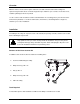
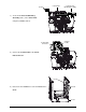
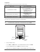
1) Turn OFF the Power Switch and unplug the Power Switch power cord from the AC Receptacle. AC Receptacle 2) Press down on the Catch, then pull forward to remove Catch the Door. Door Cover 3) Raise the Cover. Loosen both Hinge Screws. Remove the three Cover Screws, Hinge Screws and then lift the Cover off the printer. Remove any media and ribbon from the printer.
Plug Center Plate Aperture 4) Remove the Plug from the Center Plate Aperture. Screws Center Plate Aperture Cable Assembly Nuts 5) Secure the mini-din connector of the Cable Assembly (Item 5) to the Center Plate Aperture using two Screws (Item 4) and two Nuts (Item 3). Backplane CCA J13 6) After routing the Cable Assembly away from movable parts, attach its 8-pin connector to J13 of the Backplane CCA.
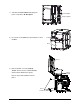
Screws Center Plate Scanner and Mounting Assembly 7) Secure the Scanner and Mounting Assembly (Item 1) to the Center Plate using three Screws (Item 2). Scanner Cable Center Plate Connector 8) Connect the Scanner Cable to the Center Plate Connector. Fascia 9) Remove the five Screws that secure the Fascia to the Screws Cover.
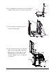
Fascia 10) Press the Tabs of the Lens together. Then slide the Lens off Lens the Fascia. (Store the Lens in a safe place, for future use.) Tabs Fascia 11) Secure the Fascia to the Cover using the five previously removed Screws. Screws Cover 12) Lower the Cover onto the printer. Reinstall and tighten the three Cover Screws. Tighten both Hinge Screws. Reinstall the Door and lower Hinge Screws the Cover. Plug the power cord into the AC Receptacle. Align the scanner; see “Alignment” section, below.
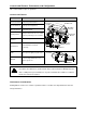
Controls and Features, Performance, and Configuration This section includes topics on operations. Controls and Features Item Function Connector Cable Horizontal Mount Mounting Bracket Location Scanner to printer interface. Connector Cable Thumbscrew Lateral position adjustment. Mounting Bracket Horizontal support. Spring-loaded holder, also for vertical Pivoting Mount Horizontal Mount Scanner positioning (scan resolution). CCD scanning device.
Integrity and Speed If the primary objective is to ensure that correct data is read over a significant region of the symbology, maximize integrity by (1) increasing the REDUNDANCY LEVEL or the MIN READABLE HEIGHT setting, (2) slowing the print speed, and (3) increasing the bar code height. When emphasizing data accuracy, the allowable maximum throughput rate may be affected.
Configuration A printer equipped with the Linear Scanner arrives with these default settings: Menu Location Function and Default Setting MODE = Auto BARCODES = All, except IATA and codes with certain addendums BAR CODE COUNT = 00 (Auto Mode) MIN READABLE HEIGHT = Disabled REDUNDANCY LEVEL = 2X IGNORE NO DATA = Disabled PRINTER OPTIONS SCANNER SYSTEM SETTINGS FAULT HANDLING FAULT HANDLING = Standard VOID DISTANCE = 0.
Scanner Menu Item Description MODE Sets device power-up detection: ENABLED Detection is performed: If found, normal printing and scanning occurs; or, if not found, a fault will be declared. DISABLED No detection is performed and no scanning functions will occur.
Scanner Menu Item REDUNDANCY LEVEL (1X – 6X) READ BARCODE 2X AUTO IGNORE NO DATA Description Ensures bar code integrity by specifying a redundant read count. This count (1 – 6) sets the number of consecutive and identical decodes that must occur for a bar code to pass. Operation switches to MIN READABLE HEIGHT. Allows an override of the verification function, where: DISABLED Checks for correct bar code data in the bar code(s). ENABLED Ignores the data present in the bar code(s).
Fault Handling Menu Item Description Increases throughput when bar codes reside near the trailing edge (in the print direction) of the label. DELAYED SCAN FAULT VOID RETRY & CONT. VOID DISTANCE (0.10 to 2.00 in.) Note: VOID is printed if faulted, with reprint attempts occurring automatically, until the RETRY COUNT has been exceeded and then that label will be skipped (discarded) and printing will continue to the next label in queue. Sets the distance to backup and print VOID on a faulted label.
A - Is the device type: S = Linear Scanner B - Is the resulting status: C = entire label complete; F = faulted (failed) label; and, U = unknown. C - Is the number of expected reads, given in two characters. D - Is the number of good reads, given in two characters. E - Is the printer’s internal Job and Sub Job Identifier, given in four characters each. F - Is the data that was read, delimited with semicolons (;) on multiple reads.
Alignment Although normally not required if factory-installed, scanner alignment may be necessary under certain circumstances: If the scanner option was just field-installed; If the original alignment has been changed (e.g., if the scanner was lowered to the 5-Mil Position); or, If the exit angle of the labels has changed (e.g., if an output device such as an external rewinder has been added).
Scanner LED Printhead Assembly Picket Fence Bar Code Note: Ensure that the Scanner is enabled in the following steps. 5) Press MENU. Press DOWN or UP to scroll to DIAGNOSTICS and then press Enter. Scroll to OPTIONS TESTING and press ENTER. Scroll to TEST SCANNER and press ENTER. Select ALIGNMENT TEST and press ENTER.
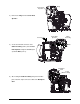
8) Slightly raise the Pivoting Mount. Loosen the Locking Screws and the Mounting Adjustment Screw enough to allow the Scanner to be positioned. Carefully lower the Pivoting Mount. Re-center the Scanner over the label and tighten the Thumbscrew.
10) Proceed according to the Scan Position: 10-Mil Position: Carefully tighten the Mounting Adjustment Screw. Mounting Adjustment Screw 5-Mil Position: Carefully tighten the Locking Screw on the right side of the Scanner.
11) Proceed according to the Scan Position: 10-Mil Position: Carefully raise the Pivoting Mount and then tighten the Locking Screw. Carefully lower Locking Screw the Pivoting Mount. Pivoting Mount 5-Mil Position: Carefully tighten the Mounting Adjustment Screw.
12) Proceed according to the Scan Position: 10-Mil Position: Loosen the Mounting Bracket Thumbscrew Pivoting Mount Thumbscrew and slide the Scanner to the rightmost position on the Mounting Bracket. Carefully raise the Pivoting Mount and then tighten the left Locking Screw. Lower the Pivoting Mount. Locking Screw 5-Mil Position: Loosen the Thumbscrew Mounting Bracket Thumbscrew Pivoting Mount and slide the Scanner to the rightmost position on the Mounting Bracket. Tighten the left Locking Screw.
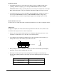
Scan Resolutions Capable of scanning 5- or 10-mil symbologies, the scan resolution is determined by the Linear Scanner’s height above the label surface. Most typically set for a 10-mil resolution, in order to scan 5-mil bar codes, the scanner must be repositioned then aligned as follows: Note: In the 5-Mil position, the available scan width is reduced to approximately 3.5 inches (89 mm). 1) Turn OFF and unplug the printer.
Troubleshooting Use the table below to locate a description of the symptom that best fits the problem and then find a corresponding solution. The Linear Scanner contains no user serviceable parts. All product service must be performed by Datamax-O’Neil. Opening the device will void the warranty and could expose CAUTION the hazardous LED light. Note: Press FEED to clear a fault. Problem No faults are generated when scanning.
Problem Scanner Faults are generated Possible solution… Try the following – when scanning. Examine the print quality of the failed label: If the bar code(s) appear(s) to be free of voids with sufficient quiet zone space, ensure that the scanner is down, Note: • Faults are normal when centered over the labels, and secured with the Thumbscrew. Dirt or debris could be covering the scanner window: Turn OFF the printer.
Specifications Physical Case Material Steel (Black) Dimensions (L x H x W) 47 x 20 x 55 mm (1.95 x 0.78 x 2.2 in) Cable Length Mini DIN Connector 7.
Warranty Information Warranty Service Procedures Datamax-O’Neil warrants to Purchaser that under normal use and service, the Scanner purchased hereunder shall be free from defects in material and workmanship for a period of one year (365 days) from the date of shipment by Datamax-O’Neil. Expendable and/or consumable items or parts such as lamps and fuses, are not covered under this warranty.