92-2427-01 Rev.
Overview This document describes the installation and use of the General Purpose Input Output (GPIO) option for the H-Class printer. After verifying the kit contents and tools needed, follow the steps to install and begin using the option. For safety and to avoid equipment damage, turn OFF the power switch and CAUTION unplug the AC power cord from the printer before starting this installation.
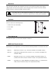
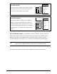
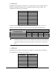
COM C RS-232 Cables Part # 32-2301-01 Part # 32-2300-01 COM D RS-232 Cable Host DB-9S Printer RJ45P +5 VDC +5 VDC 1 1 RXD 2 4 TXD TXD GROUND 3 5 RXD 5 3 GROUND DTR 4 DSR 6 2 RTS CTS 8 9 NC 7 NC NC Part # 32-2603-00 2 7 CTS 8 DTR 6
Step 1: Configuring the Hardware Configure the card to meet your interfacing requirements by arranging hardware jumpers, as described in the following procedure: Always wear a wrist strap and follow standard ESD prevention measures CAUTION when handling the card. A) Remove the card from the packaging and then place the card onto a static-free work area.
For direct inputs – GPI/O A - J1 Use the printer’s +5VDC and Ground to supply the devices interfacing to the GPI/O A inputs (as shown in the sample circuit, right).
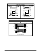
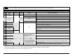
Failure to properly configure the GPIO Port can result in damage to the printer and / or connected devices. WARNING GPI/O Port A Jumper Overview Pin 1 Signal Name Direction Ground [1] Jumper JMP 8 +5 VDC Installed Removed JMP 9 Removed Start Of Print 4 Slew Label 5 Toggle / Pause Reprint 7 +24 VDC 8 Ground 9 Ribbon Low 10 Service Required 11 End Of Print 12 Media Out 13 Ribbon Out 14 Data Ready 15 Option Fault Ground must be supplied. Note: Drawing more than .
► GPI/O B (J2) Six unassigned inputs are designed to interface to open-collector outputs. These inputs require no external pull-ups, while blocking diodes allow the use of totem pole outputs from +4.5 VDC to + 26 VDC. Optical isolators provide galvanic isolation. Two print control interface circuit examples are given below.
Failure to properly configure the GPIO Port can result in damage to the printer and / or connected devices. WARNING GPI/O Port B Overview Pin 1 Signal Name / Direction [1] Jumper +5 VDC JMP 11 2 Input 6 N/A 3 Input 3 N/A Position Installed Removed 4 Output 6 JMP 7 N/A N/A 6 Output 3 JMP 4 Note: Drawing more than .5 amps can cause unreliable printer operation. +5VDC must be supplied. Programmed input function. Programmed input function. Programmed output function pulled-up to +5VDC.
► COM C (J4) Recognized by the printer as Serial Port C, COM C functions as an auxiliary RS-232 interface or dedicated device port for the RFID and Linear Scanner options. Pin assignments for the port are as follows: Pin Number COM C (J4) 1 +5V (@ .5 amps) 2 RX 3 TX 4 DTR 5 Ground 6 Ground 7 RTS 8 CTS 9 N/C At default settings, the COM C port automatically selects its function.
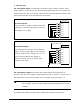
Step 2: Installing the Option Install the GPIO Card as described below: A) Turn OFF the Power Switch and unplug the power cord from the AC Power Switch Receptacle. AC Receptacle Screws Card Cage B) Remove the two Screws that secure the Back Panel to the Card Cage, and then remove the Back Panel. Back Panel Card Cage Slot C) Slide the GPIO Card (Item 1), GPIO Card Notch down, into the leftmost Card Cage Slot.
Card Cage Cover Plate D) Place the Cover Plate (Item 2) onto Screws the Card Cage, as shown, then install and tighten the two Screws (Item 3) to secure the plate.
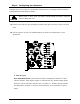
Step 4: Configuring the Software Settings Configure the printer’s menu settings for the option’s operation.
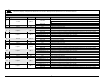
Input Monitor – Display incoming GPIO binary signal states using the ADVANCED MENU DIAGNOSTICS OPTIONS TESTING TEST GPIO MONITOR GPIO INPUT selection. GPIO A Signals SOP 1 FEED 1 i1 0 i2 1 PAUSE 0 i3 0 REPRT 0 i4 1 i5 1 i6 1 GPIO B Signals Note: Unused, non-connected inputs will have an indeterminate state, and may assume a value of 1 or 0.