Operator’s Manual Professional and Professional+ Models Professional+ Professional
Copyright Information CG Triumvirate is a trademark of Agfa Corporation. CG Times based upon Times New Roman under license from the Monotype Corporation. Windows is a registered trademark of the Microsoft Corporation. All other brand and product names are trademarks, service marks, registered trademarks, or registered service marks of their respective companies.
Agency Compliance and Approvals UL60950-1, Second Edition, Information Technology Equipment CSA C22.2 No. 60950-1-03, Second Edition C US Listed The manufacturer declares under sole responsibility that this product conforms to the following standards or other normative documents: EMC:EN 55022 (2006) Class A EN 50024 (1998) IEC 60950-1 :2001, Second Edition Safety:This product complies with the requirements of IEC 60950-1:2001, Second Edition Gost-R GB4943-2001, GB9254-1998, GB17625.
Contents 1 1 G Geettttiin ng gS Sttaarrtteed d............................................................................................................................................................................1 1 1.1 Introduction ........................................................................................................ 1 1.2 Unpacking the Printer ........................................................................................... 1 1.3 Kensington Security Slot ............
4 4 M Meen nu uS Syysstteem m..............................................................................................................................................................................3 35 5 4.1 Menu System Overview ....................................................................................... 35 4.2 The User Menu................................................................................................... 35 4.3 The Advanced Menu........................................
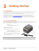
1 Getting Started 1 1..1 1 IIn nttrro od du uccttiio on n The E-Class Mark III printer (hereafter referred to as “the printer”) is user-friendly thermal printing device that blends quality and durability in an affordable package to meet all of your labeling needs. This manual provides the information necessary to operate and maintain the printer. To begin printing labels or tags, refer to the instructions included with your software labeling program.
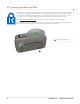
1 1..3 3 K Ke en nssiin ng gtto on nS Se eccu urriitty yS Sllo ott Professional + modules equipped with the Key Lock Option also include a built-in Kensington Security Slot with a metal backing plate. The Kensington slot allows you to physically secure the printer from being stolen by tethering it to a larger object like a desk or counter. There are many security solutions offered by Kensington that are compatible with the slot. Visit http://www.kensington.
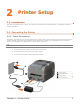
2 Printer Setup 2 2..1 1 IIn nttrro od du uccttiio on n This section explains how to connect your printer and load media (including ribbon, if equipped for thermal transfer operation). 2 2..2 2 C Co on nn ne eccttiin ng g tth he eP Prriin ntte err 2.2.1 Power Connections The printer is powered by an external auto-ranging power supply, which connects between the printer and an electrical outlet.
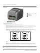
2.2.2 Interface Connections Before connecting interface cables to the printer, ensure that the Power Switch is in the OFF (O) position. 312 Ethernet Port USB Port Serial Port USB Host Port Parallel Port Cable Requirements Choose the correct cable when interfacing the printer to the host: The Parallel Port (optional) supports parallel communications via a 36-pin male mini-Centronics connector.
2 2..3 3 LLo oa ad diin ng gM Me ed diia a The printer is equipped with an Adjustable Media Sensor and may require adjustment to match your media choice, refer to Section 4.4. 2.3.1 Loading Roll Media Load media as follows: 1) Pull forward on the Cover Latches and lift up on the cover. Pro+ models have Key Lock option that must be unlocked before the cover can be opened. 312 Cover Latches Key Lock Option (Pro+ models only) 2) Slide the Media Guides outward.
4) Pull out enough media to exit the front of the printer. Adjust the Media Guides so they are lightly touching the edge of the media. 5) If using thermal transfer media (ribbon) proceed to Section 2.4 Loading Ribbon. Otherwise close the printer’s Cover and press downward until latched. Pro Pro+ models are equipped with a Cover Release Latch. Press outward on the latch to release cover.
2.3.2 Loading - External Media Using Internal Media Chute Guides Accessory (Professional model only) Load media as follows: 1) Slide the Media Guides outward. 2) Slide the Media Hangers outward and install the two Media Chute Guides into the Media Hangers. Media Chute Guides Media Hangers External Media Guide 3) Position the Media Hangers to match the width of the media being used. Slide the Hanger Lock against the Media Hanger to hold this position.
4) Route the media through the External Media Slot in the rear of the printer. Pull out enough media to exit the front of the printer. Adjust the Media Guides so they are lightly touching the edge of the media. External Media Slot Media Guides External Media Supply 5) If using Thermal Transfer media (ribbon) proceed to Section 2.4 Loading Ribbon. Otherwise close the printer’s Cover and press downward until latched.
2.3.3 Loading Media with the Peel and Present Option Load media for peeling (if the printer is equipped with the option) as follows: When using the Peel Mechanism do not exceed a print speed of 4 IPS. To utilize “Tear mode” with Peel and Present Option installed; move the Peeler Door to its open position. 1) Load media as described in Section 2.3, (steps 1-3). 2) Remove about 8 inches (200mm) of labels from the Media Backing. 3) Open the Peeler Door.
2.3.4 Loading Media with the Cutter Option Load media for cutting (if the printer is equipped with the option) as follows: 1) Load media as described in Section 2.3, (steps 1-3). 2) Route the media through the opening in the Cutter. 312 Cutter Media 3) If using Thermal Transfer media (ribbon) proceed to Section 2.4 Loading Ribbon. Otherwise close the printer’s Cover and press downward until latched. 4) Press the button to advance the media (if the Fault Light is lit, see Section 3.7.).
2.3.5 Adjustable Media Core Hangers (Pro+ models only) The Adjustable Media Core Hangers allow for support of media rolls with 3”, 1.5”, or 1” cores. To adjust: 1) Pull outward in on the Core Hanger and slide the Core Hanger up or down to the desired setting. Be sure both core hangers are set to the same position. 312 Chapter 2 – Printer Setup Media Hanger Core Hanger 3”, 1.
2 2..4 4 LLo oa ad diin ng gR Riib bb bo on n The printer is capable of using C.S.I (Coated Side In) and C.S.O (Coated Side Out) ribbons in the following configurations: ½” Core Ribbons Ribbon Core Width: 4.3 inches (110mm) Ribbon Width: 1.0 - 4.3 inches (25 - 110mm); Centered on core 1” Core Ribbons (with Ribbon Core Adapters, see section 2.4.1.) Ribbon Core Width: 1.0 - 4.3 inches (25 - 110mm); Centered on Ribbon Core Adapters Ribbon Width: 1.0 - 4.
2) Push out the Supply Hub and load the Supply Roll into the printer as shown. Depending on the size of the Supply Roll, the Media Bouncer may need to be pushed out of the way. 3) Once the Supply Roll is loaded, slide the Ribbon Handler Latch downward to unlatch the Ribbon Handler Assembly. 312 Supply Roll Supply Hub Media Bouncer Ribbon Handler Latch Ribbon Handler Assembly 4) Push out the Take-up Hub and load an empty Ribbon Core into the printer as shown.
5) Route the ribbon from the supply roll to the Ribbon Core, as shown below. 6) If not already attached, affix the leader of the ribbon to the Ribbon Core using Tape. Rotate the Take-up Hub Wheel several times to secure the ribbon. 312 Ribbon Core Tape Take-up Hub Wheel 7) Raise and latch the Ribbon Handler Assembly. Close the cover and press the the media (if the Fault Light is lit, see Section 3.7.
2.4.1 Using the Ribbon Core Adapters When using ribbons with a 1” (25.4mm) I.D. core, a Core Adapter must be used. 1) Slide the Ribbon Roll (with the leader positioned as shown above) onto a Core Adapter. Slide an empty Ribbon Core onto the remaining Core Adapter. 312 Core Adapter Ribbon Roll Ribbon Core 2) If using a narrow ribbon, position the Ribbon Roll so that it is centered on the Core Adapter. The Core Adapters are marked in both inches and centimeters to aid in proper positioning.
16 Chapter 2 – Printer Setup
3 Printer Operation 3 3..1 1 IIn nttrro od du uccttiio on n The Front Panel consists of a graphic display, two indicator lights, four directional arrow buttons and one multi-function button, as detailed in the following sections. 312 Green/Orange Status LED Red Error LED Graphic Display Directional Arrow Buttons Multi-function Button 3 3..
3 3..3 3 U Usse err IIn ntte errffa acce e The User Interface is divided in three sections, Feed/Pause, Test, and Menu. Button functions are dependent on the mode currently in use. Use the Up and Down arrow buttons to scroll to the item and then press the center button to enter that menu mode. 312 Time/Date Printer Mode Programmable Marquee (See Programmer's Manual for displaying a custom message) 3.3.1 Feed/Pause Mode At idle: Feeds the media to the next label.
Enters the Test mode menu/sub-menu items. Prints the chosen test label. Scrolls upward to the next menu item. Increments the Count value. Scrolls downward to the next menu item. Decrements the Count value. Exits the Test menu mode Displays the ‘Count’ screen. 3.3.3 Menu Mode The menu mode is covered in detail in Chapter 4. Enters the Menu mode menu/sub-menu items. Enter/Accepts current prompt. Scrolls upward to the next menu item. Increments the current value. Scrolls downward to the next menu item.
3 3..4 4 P Prriin ntte err C Co on nffiig gu urra attiio on nT To oo ollss The printer contains many user adjustable parameters. These parameters are configurable using a few methods. The table below lists the most popular ways of configuring the printer and the advantages of each. Choose the method that best addresses your application.
3 3..5 NE 5 P ET Tiirra Prriin aC ntte CT err C T)) Co on nffiig gu urra attiio on nU Uttiilliitty y ((N NETira CT (located on the Accessories CD-ROM) is a Windows-based configuration utility that allows the user to make changes to the existing printer setup via a direct connection to the host computer’s serial, USB, Ethernet, or parallel ports.
NETira CT Usage 1) Once installed launch the NETira CT configuration utility: 2) Be sure the printer is ‘ON’. Connect the host to the printer (see Section 2.2.2 Interface Connections). For Serial Connections: a) Query the printer by using the ‘Auto Detect’ button. This will connect to the printer and retrieve the setting currently stored in the printer. For USB and Parallel Connections: Close the ‘Open a configuration file…’ dialogue box.
3) At this point you may browse the Printer Component categories and make any changes necessary to the printer configuration. 4) Once complete, send the new settings to the printer using the ‘Send’ button. Note: When sending the changes to the printer, only the changes displayed on the current page will be sent. You must click the ‘Send’ button for each page that has been modified.
3 3..6 6 W Wiin nd do ow wss D Drriiv ve err The Windows driver is located on the Accessories CD-ROM included with your printer. For the latest version please visit our web site at http://www.datamax-oneil.com Be sure your printer’s firmware version is 9.03_0016B or greater. Firmware is available from our website, for the latest version please visit our web site at http://www.datamax-oneil.com Be sure your printer’s USB Mode is set to “Printer”.
Important Notes: The Windows driver functions the same as any other Windows printer. While built-in help files provide information on all settings, there are some important setting parameters that should be observed for trouble free printing: Page Setup Tab: Stock Options Tab: Print Speed & Printhead Temperature It is important that the Stock setting matches the size of the label you are using. If you cannot find a match for your label click New and enter the dimensions of your label.
3 3..7 7 M Me ed diia aC Ca alliib brra attiio on n 3.7.1 Quick Calibration Ensure the printer is properly loaded with media, proceed with calibration as follows: This calibration is not necessary when using continuous stock. Media containing large gaps may require a change in the Paper Out Distance before proceeding. Calibrate the printer as follows: Step A Action Displayed Message Comment Wait briefly for initialization to complete. Turn ON the printer.
3.7.2 Manual Calibration The Manual Calibration can be performed using the NETira CT Utility (see Section 3.5) or using the front panel buttons via the printer’s menu, see Section 4.4. Manual Calibration provides dynamic readings, which can be helpful when using media with small positioncritical notches or marks. Calibrate the Media Sensor using the steps below: Step A Action Displayed Message Comment Wait briefly for initialization to complete. Turn ON the printer.
3.7.3 Advanced Entry Calibration Advanced Entry is an alternate calibration method for special-case media types, where sensor readings are taken using different sampling algorithms and from a list of these readings the best algorithm is selected for manual entry into the database. Advanced Entry Calibration should be used only when Manual Calibration proves unsuccessful.
Advanced Entry Calibration (continued) Step Action Displayed Message Using the or button, set the Gain Number to 0. F TRAN SENSOR GAIN 0 253 (0 - 31) Record the sensor reading as a Label Value for Gain Number 00 in a table (32 rows by four columns, with headings similar to those shown below.) Comment This is the Label Value for a gain setting of 0.
Advanced Entry Calibration (continued) Step Action Displayed Message Raise the cover assembly then proceed according to the media type: H Die-cut – Remove a label or two from the liner then position the liner in the Media Sensor. Notched – Position the Media in the Media Sensor under the notch.
Advanced Entry Calibration (continued) Step Action J button, increment the Using the Gain Number by one. Record the TOF Value. Repeat this process for each Gain Number. Displayed Message TRAN SENSOR GAIN 1 245 (0 - 31) Comment These are TOF Values, where “245” represents the current sensor reading.
Advanced Entry Calibration (continued) Step Action Displayed Message L Using the or button, set the Gain Number determined in the previous step. Press the button to enable the setting. OK Comment This example uses Gain Number 18. button again to rePress the enter the TRAN SENSOR GAIN (or REFL SENSOR GAIN, if using reflective media) menu item. Complete a table (see example below) using new measurements, as follows: M (A) Raise the Cover Assembly.
Advanced Entry Calibration (continued) Step Action Displayed Message Comment button to exit the current menu level. Press the N Using the button, scroll to PAPER SENSOR LEVEL (or if using reflective media, REFL PAPER LEVEL) and then press the button. PAPER SENSOR LEVEL 174 (0 - 255) This is the Paper value. Using the or button, set the Paper value determined in Step M and then press the button.
34 Chapter 3 – Printer Operation
4 Menu System 4 4..1 1 M Me en nu uS Sy ysstte em mO Ov ve errv viie ew w The Menu System contains two modes, each with a differing level of access to secondary menus or functions: The User Menu accesses basic printer settings and functions The Advanced Menu accesses all operational settings, functions, and diagnostics Prompts may appear before menu access is granted and before changes are enacted; see Security for details. 4 4..
4 4..3 3 T Th he eA Ad dv va an ncce ed dM Me en nu u The Advanced Menu contains all setting, control, and functional selections in these menus: Media Settings Print Control Printer Options System Settings Communications Diagnostics After selecting the Advanced Menu, it will be shown whenever the MENU branch is accessed. To enable the Advanced Menu, proceed as follows: 1. Press the button to scroll to MENU and then press the button. 2.
4 4..4 4 M Me en nu uD De etta aiillss Media Settings The Media Settings menu contains label and ribbon sensing and sizing functions, as well as printhead cleaning selections: Media Type Media Index Type Auto Calibration* Label Length Maximum Label Length* Paper Empty Distance* Label Width Ribbon Low Options* Sensor Calibration* Printhead Cleaning* Items denoted with an asterisk (*) are only accessible through the Advanced Menu.
DISPLAYED ITEM RIBBON LOW OPTIONS RIBBON LOW DIAMETER 0.50 PAUSE ON RIBBON LOW ENABLE DISABLE SENSOR CALIBRATION QUICK CALIBRATION MANUAL CALIBRATION ADVANCED ENTRY PAPER SENSOR LEVEL REFL PAPER LEVEL GAP SENSOR LEVEL MARK SENSOR LEVEL EMPTY SENSOR LEVEL TRAN SENSOR GAIN REFL SENSOR GAIN PRINTHEAD CLEANING CLEAN HEAD SCHEDULE CLEAN HEAD COUNTER RESET COUNTER CLEAN HEAD NOW 38 ITEM DESCRIPTION Defines the printer response when THERMAL TRANSFER mode is selected and the ribbon supply begins to diminish.
Print Control The Print Control menu contains printing throughput, offset and custom setup functions: Heat Print Speed Feed Speed Reverse Speed* Slew Speed* Row Offset Column Offset Present Distance TOF Precedence* Custom Adjustments* Items denoted with an asterisk (*) are only accessible through the Advanced Menu.
Printer Options The Printer Options menu contains file-handling, module, and optional equipment settings: Modules Present Sensor Cutter The menu selections are defined as follows: DISPLAYED ITEM MODULES DIRECTORY PRINT FILE ITEM DESCRIPTION Controls memory handling functions, where: Allows viewing and printing of the available space and file types (including plug-in files) present on a module. Only detected modules will be listed, and selecting ALL will display all results.
System Settings The System Settings menu contains label formatting, operation, and control functions: Menu Mode Configuration File Internal Module* Default Module* Scaleable Font Cache* Single Byte Symbols* Double Byte Symbols* Time And Date Media Counters* Print Configuration* Configuration Level* Set Factory Defaults* Format Attributes* Label Rotation Imaging Mode* Pause Mode* Peel Mode* Security* Units Of Measure* Input Mode* User Lab
DISPLAYED ITEM ITEM DESCRIPTION SCALEABLE FONT CACHE 384 KBytes Configures the number of 1KB blocks (128 - 512) allocated for the scaleable font engine, where: SINGLE BYTE SYMBOLS Selects the code page used to print single byte fonts, including: Is the Default Setting.
DISPLAYED ITEM CONFIGURATION LEVEL ITEM DESCRIPTION Displays the hardware and software levels of the printer, where: PRINTER KEY This information is also provided on the Configuration Label. Identifies the unique key number of the printer, in the form: vvvv cwxx c w xx yyyyyy zzz vvvv-cwxx-yyyyyy-zzz, where: Represents the printer model number. Represents the hardware/software feature level, where: Represents the printer class. Represents hardware feature level of the main board.
DISPLAYED ITEM ITEM DESCRIPTION UNITS OF MEASURE IMPERIAL METRIC Sets the measurement standard used, where: Uses inches. (Default Setting) Uses millimeters and centimeters. INPUT MODE DPL LINE PL-Z Defines the type of processing that will occur when data is received, where: Processes data for standard DPL printing. Processes data for Line Mode (template) printing.
DISPLAYED ITEM COLUMN EMULATION XXX Dots ROW EMULATION XXX Dots SOP EMULATION DISABLED 110 (PRODPLUS) 220 (ALLEGRO) 250 (PRODIGY) BACK AFTER PRINT MODE ITEM DESCRIPTION Allows the column dots per inch to be adjusted (153 - 253 dots), so that numbers smaller than the printhead resolution reduce the printed output from right to left, where: Default setting is dependant on printer model.
Communications The Communications menu contains interface and host control functions: Serial Port A* Parallel Port A* USB Port* Network/Bluetooth* Host Settings* Items denoted with an asterisk (*) are only accessible through the Advanced Menu.
DISPLAYED ITEM NETWORK/BLUETOOTH ACTIVE INTERFACE ITEM DESCRIPTION Controls the communications settings for the network and Bluetooth interfaces, where: Selects the network interface currently in use by the printer, where: NONE Disables all interfaces WIRED ETHERNET Selects the Wired Ethernet interface WIRELESS ETHERNET Selects the Wireless Ethernet interface (if installed) BLUETOOTH Selects the Bluetooth interface (if installed) WIRED ETHERNET IP DISCOVERY USE STATIC ADDRESSES USE DHCP Controls
DISPLAYED ITEM WIRELESS ETHERNET IP DISCOVERY USE STATIC ADDRESSES USE DHCP ITEM DESCRIPTION Controls the communications settings for the wireless Ethernet network interface, where: Sets the address discovery method, where: The stored static IP, Subnet Mask, and / or Gateway Address will be used. The card broadcasts over the network using DHCP protocol to receive addresses from the responsible server at startup.
DISPLAYED ITEM HOST SETTINGS ITEM DESCRIPTION Controls the communications with a host device, where: HOST TIMEOUT Sets the number of seconds (1 - 60) that an established communications port must be idle before data can be received through an alternate port, where: 10 The "ignore host" settings for ESC SEQUENCES, HEAT, SPEED, TOF SENSING, SYMBOL SET, CNTRL-CODES, STX-V SW SETTINGS, and MAX LENGTH will be unaffected when PL-Z Mode is selected (see Input Mode for details).
Diagnostics The Diagnostics menu contains testing functions and printhead reporting selections: Hex Dump Mode* Options Testing* Print Test Rate (min)* Sensor Readings* Ribbon Sensor Limits* Flash Module Report* Items denoted with an asterisk (*) are only accessible through the Advanced Menu.
Maintenance & Adjustments 5 5 5..1 1 IIn nttrro od du uccttiio on n This section details the cleaning, adjusting, and troubleshooting tips for the printer. The following table outlines the recommended maintenance schedule for the various printer parts. Area Method Interval Printhead Turn OFF the printer before cleaning the printhead. Use solvent* applied with a cotton swab to clean the printhead from end to end. After every roll of media. Platen Roller Turn OFF the printer.
5 5..2 2 C Clle ea an niin ng g tth he eP Prriin ntth he ea ad d Never use a sharp, hard, or abrasive object on the printhead. If print quality declines (symptoms can include unreadable bar codes or streaks through text and graphics), the typical cause is debris buildup on the printhead which, left unattended, can lead to premature dot failure. Depending upon the supplies and printing parameters used, different cleaning methods are recommended. Streaks can indicate a dirty or a faulty printhead.
Cleaning Card Procedure If printing with direct thermal media, thermal transfer media with wax/resin ribbon combinations, or if the Cotton Swab technique was not successful, clean the printhead as follows: 1) Open the printer. Wait briefly for the Printhead to cool. 2) Remove media and ribbon then place a Cleaning Card under the Printhead (part number 70-201301). 3) Close the cover then press the button to initiate cleaning.
5 5..3 3 R Riib bb bo on nT Te en nssiio on nA Ad djju ussttm me en ntt The adjustable ribbon handler feature, found on printers equipped with the thermal transfer option, allows the optimum amount tension to be supplied by the ribbon supply hub. Adjust the ribbon tension as follows: 1) Turn ‘off’ the printer. 2) Hold the ribbon/ribbon hub to prevent it from turning. Then push in and rotate the Ribbon Tension Adjustment Knob to the position that matches the core size of the ribbon in use.
5 5..4 4 A Ad djju usstta ab blle eM Me ed diia aS Se en nsso orr The optional Adjustable Media Sensor (AMS) allows the printer to accept a wider variety of media configurations. The table below defines general AMS positions for various media and Top of Form (TOF) types. AMS Positioning Media Type Continuous Die-Cut Sensor Location TOF Sensing Method Any location in the media path with both sensors aligned. Any location within the media path where the gap between the labels crosses the sensors.
5 5..5 5 P Prriin ntth he ea ad dR Re ep plla acce em me en ntt If the Printhead becomes damaged or worn, replace it as follows: Always follow proper Electro Static Discharge procedures when replacing the printhead. 1) Turn OFF the printer and remove the ribbon if installed. 2) Lower the Ribbon Handler Assembly. 3) Press outward on the two Printhead Carrier Tabs and rotate the Printhead Carrier down.
5) Loosen the Printhead Screw and allow the Printhead to fall free. 6) Remove the Printhead Cable. 312 Printhead Shield Printhead Screw Printhead Printhead Cable Sensor Installation: 1) Carefully connect the Printhead Cable to the new Printhead. 2) Position the Printhead in the Printhead Carrier and tighten the Printhead Screw. 3) Ensure the Sensor properly seated and rotate the Printhead Shield upward until it snaps into place. 4) Rotate the Printhead Carrier upward until it snaps into place.
5 5..6 6 P Plla atte en nR Ro olllle err R Re ep plla acce em me en ntt The Platen Roller can be easily removed for cleaning, replacement, or clearing media jams. 1) Turn OFF the printer and remove the media if installed. 2) Lift up on the two Platen Roller Tabs. 312 Platen Roller Tabs Platen Roller Assembly 3) Remove the Platen Roller Assembly from the printer. 312 Installation: 1) Position the Platen Roller Assembly into the printer.
5 5..7 7 U Up pd da attiin ng gF Fiirrm mw wa arre e When program updates and/or new features are added, they can be downloaded to the printer as follows: 1) Identify the new version for your model of printer from the Datamax-O’Neil Web site at www.datamax-oneil.com and download it onto your computer’s hard drive. 2) Launch the NETira CT configuration utility, and query (connect) to the printer, (see section 3.5 for more information on NETira CT).
60 Chapter 5 – Maintenance Adjustments
6 Troubleshooting 6 6..1 1 IIn nttrro od du uccttiio on n Occasionally, situations arise that require troubleshooting. Possible problem situations and potential solutions are listed below. Contact a qualified technician for problems that persist or problems not covered in this section. 6 6..2 2 T Trro ou ub blle essh ho oo ottiin ng gT Tiip pss The following section lists the symptoms and the associated page numbers of the topics covered.
Skips every other label (print quality is good, but every other label is skipped): The label is formatted too close to the top edge of the label: Leave white space equal to 8-dot rows (about .02 inch [.5mm]) at the top of the label. The media is not calibrated: Calibrate it (see Section 3.7). The media sensor or media sensor circuitry may be defective: Call for service.
6 6..3 3 H He ex xD Du um mp pM Mo od de e The Hex Dump Mode is a useful tool for diagnosing problems, including communication and DPL syntax errors, allowing a comparison of input strings (sent by host) to output data (received by printer). To decode this information, the Programmer’s Manual is an essential reference. This output can be used for debugging the label format. In addition, by repeatedly sending a format, this mode can uncover handshaking problems (if they exist).
64 Chapter 6 – Troubleshooting
A Specifications Mechanical Width Pro Models: 8.01 inches (20.4 cm) Pro+ Models: 8.54 inches (21.7 cm) Depth Pro Models: 11.10 inches (28.2 cm) Pro+ Models: 14.17 inches (36.0 cm) Height Pro Models: 7.36 inches (18.7 cm) Pro+ Models: 9.45 inches (24.0 cm) Weight Pro Models: 5.25 pounds (2.4 kg) Pro+ Models: 7.75 pounds (3.
Media / Ribbon Media Types Roll-Fed, Die-Cut, Continuous, Fan-Fold Max. Media Width 4.4 inches (110mm) Min. Media Width 0.75 inches (19mm) Max. Print Width 203 DPI Models: 4.25 inches (108mm) 300 DPI Models: 4.12 inches (106mm) Print Length Range .236 – 99 inches (6 - 2514mm) Minimum Label Height Tear: 0.5 inches (12mm) Peel: 1.0 inches (25mm) Cut: 1.18 inches (30mm) Media Thickness Range .0025 - .01 inches (.064 - .254mm); up to .005 inches (.
Approved Media To achieve optimum print quality and maximum printhead life, Datamax-O’Neil specifies the use of DatamaxO’Neil brand media and ribbons. These supplies are specially formulated for use in our printers; use of other supplies may affect the print quality, performance, and life of the printer or its components. For a current list of approved media and ribbons for use in direct thermal and thermal transfer applications, please contact a Media Representative at (407) 523-5650.
68 Appendix A – Specifications
B Wireless and Wired LAN Setup B B..1 1 N Ne ettw wo orrk kC Ca arrd dS Se ettu up p Whether a wired or wireless connection is intended, it is recommend to establish a wired connection to the printer first. This will allow access to the printers internal web pages to configure the settings necessary for a typical wireless connection. If a wired connection is not or can not be achieved all connection parameters can also be set using the NETira CT configuration utility, see section 3.5.
B B..2 2 W Wiirre elle essss S Se ettu up p 1. Open your web browser. Type in the IP Address assigned to the printer. The printers default IP address is: 192.168.10.26. If a different IP Address has been assigned to the printer, make sure to enter the correct IP address. The following page will appear: The printer’s internal web pages are divided into 10 pages that are accessible via the navigation bar on the left-hand side. Most of the items on these pages mimic the printer's internal menu.
B.2.1 Wireless Setup – Infrastructure After a successful setup is made via a wired connection, the Wireless connection (if equipped) can now be configured in infrastructure mode using a static or DHCP issued IP address. 1. Open your web browser. Type in the IP Address of the printer. The Default IP is: 192.168.10.26. If a different IP Address has been assigned to the printer, make sure to enter the correct IP address. A page similar to the right will appear: 2.
The printer will now search for a server. Allow up to 90 seconds for the printer to retrieve an IP address. At this point it is recommended to print a Network Report. This Network Report is generated by the printer and lists important default information such as the IP and MAC Addresses as well as SSID for wireless equipped cards. To print the ‘Network Report’: Press the button to highlight the ‘TEST’ menu branch and then press the button.
5. Under the “WIFI Security and Authentication”, set any security/authentication settings necessary for your network. 6. Scroll down to the bottom of the page, enter the password (default is “sysadm”) and click Apply. 7. Click on the “General Network Settings” menu item on the left side of the screen. Locate and set the following items: 8. In the “Network Interface”, select the “Wireless Ethernet” radio button 9.
B B..3 3 IIn nsstta alllliin ng g tth he eP Prriin ntte err D Drriiv ve err Install the Printer Driver as follows (screen shots below are samples taken using Windows 2000; other versions will be similar): 1 2 Start the Windows Add Printer Wizard. The following screen should appear, and then click Next>. Make sure that Local Printer is selected and then click Next>. 3 4 Select Create a new port: and then select Standard TCP/IP Port from the drop down menu. Click Next>. Click Next>.
9 10 Insert the Accessories CDROM and click Browse. Browse to the \DRIVERS\ folder on the CD-ROM. Ensure the file “DatamaxO’Neil.inf” is selected then click OK. 11 12 Click OK. Choose your printer from the list and then click Next>. 13 14 Assign a name in the Printer name field and select whether or not it is to be your default printer then click Next>. Select whether or not to share this printer on your network. Then click Next>. 15 16 Select No then Click Next>.
76 Appendix B – WLAN & LAN Setup
C Bluetooth Setup C C..1 1 B Bllu ue etto oo otth hS Se ettu up p Bluetooth connection parameters can be set using the NETira CT configuration utility, via an established serial or wired LAN connection. Launch the NETira CT configuration utility, and query (connect) to the printer, (see section 3.3 for more information on NETira CT). 1) Click on the General Network menu branch under the Printer Component section of the configuration utility.
78 Appendix C – Bluetooth Setup
D Menu Language D D..1 1 C Ch ha an ng giin ng g tth he eM Me en nu u LLa an ng gu ua ag ge e Different languages and / or Datamax-O’Neil-provided translations can be downloaded to replace the standard (English) menu of the printer by changing the spreadsheet that defines the system dictionary. To change the language you will add a new language column (or modify the existing column) in the spreadsheet, click on the “Generate DPL file(s)” radio button, and then send that file(s) to the printer.
B. Click the “Enable Macro” box. The following screen appears: C. Click on Column J and enter the new language, or modify an existing one. Some tips on this process: •Message Size – When entering new messages, reference the “MAX” column: this is the maximum number of characters allowed for this field. (Warnings are displayed when the number of characters is exceeded, or when trying to modify the MAX value; however, if “cutting and pasting” fields, this warning system may be defeated.
F. Download the generated files to the printer – one method is the DOS copy command: copy small.ls lpt1: /b G. Reset the printer by pressing and holding the CANCEL Key for approximately four seconds. H. After resetting, verify operation by printing a Configuration Label (see Section 4.4). New language information will be printed under SYSTEM INFORMATION / OPTIONAL LANGUAGES. (Also, the new language will appear on the display as a menu item in SYSTEM SETTINGS / MENU LANGUAGE.
D D..2 2 A on n Ad dv va an ncce ed dF Fiille eH Ha an nd dlliin ng g IIn nffo orrm ma attiio 82 • The standard printer leaves the factory with EFIGS loaded into Module Y. At this point, Module Y is LOCKED and will only accept additional language downloads. • After downloading a language update, Module Y is left UNLOCKED until the printer is reset or power is cycled. In this state, Module Y will accept font, image and label format downloads. The module will also honor the Clear Module request.
The screen shot below is an example of Unicode defined languages, Chinese & Russian. Note the only additional information required is the “double” in row 1.