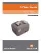
Operator’s Manual Basic and Advanced M odels Serial# 3xxxxxxx or earlier
Copyright Information CG Triumvirate is a trademark of Agfa Corporation. CG Times based upon Times New Roman under license from the Monotype Corporation. Windows is a registered trademark of the Microsoft Corporation. All other brand and product names are trademarks, service marks, registered trademarks, or registered service marks of their respective companies.
Agency Compliance and Approvals UL60950-1, Second Edition, Information Technology Equipment CSA C22.2 No. 60950-1-03, Second Edition C US Listed The manufacturer declares under sole responsibility that this product conforms to the following standards or other normative documents: EMC:EN 55022 (2006) Class A EN 50024 (1998) IEC 60950-1 :2001, Second Edition Safety:This product complies with the requirements of IEC 60950-1:2001, Second Edition Gost-R GB4943-2001, GB9254-1998, GB17625.
Contents 1 1 G Geettttiin ng gS Sttaarrtteed d ............................................................................................................................................................................1 1 1.1 Introduction ........................................................................................................ 1 1.2 Unpacking the Printer ........................................................................................... 1 2 Seettu up p ...........................
4 4 M Maaiin ntteen naan nccee & &A Ad djju ussttm meen nttss ................................................................................................................................2 27 7 4.1 Introduction ...................................................................................................... 27 4.2 Cleaning the Printhead ........................................................................................ 28 4.3 Ribbon Tension Adjustment ......................................
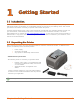
1 Getting Started 1 1..1 1 IIn nttrro od du uccttiio on n The E-Class Mark III printer (hereafter referred to as “the printer”) is user-friendly thermal printing device that blends quality and durability in an affordable package to meet all of your labeling needs. This manual provides the information necessary to operate and maintain the printer. To begin printing labels or tags, refer to the instructions included with your software labeling program.
2 Chapter 1 – Getting Started
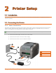
2 Printer Setup 2 2..1 1 IIn nttrro od du uccttiio on n This section explains how to connect your printer and load media (including ribbon, if equipped for thermal transfer operation). 2 2..2 2 C Co on nn ne eccttiin ng g tth he eP Prriin ntte err 2.2.1 Power Connections The printer is powered by an external auto-ranging power supply, which connects between the printer and an electrical outlet.
2.2.2 Interface Connections The printer can be connected to the host system via the parallel, serial, Ethernet or USB ports. Before connecting interface cables to the printer, ensure that the Power Switch is in the OFF (O) position. 312 Ethernet Port USB Port Serial Port Parallel Port Cable Requirements Choose the correct cable when interfacing the printer to the host: The Parallel Port (optional) supports parallel communications via a 36-pin male mini-Centronics connector.
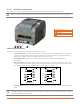
2 2..3 3 LLo oa ad diin ng gM Me ed diia a If the printer is equipped with an Adjustable Media Sensor it may require adjustment to match your media choice. If the printer is equipped with this type of sensor, proceed to Section 4.4. 2.3.1 Loading Roll Media Load media as follows: 1) Slide the Media Guides outward. 2) Slide the Media Hangers outward and insert the Roll Media as shown. Allow the Media Hangers to retract and grasp the media roll.
4) If using thermal transfer media (ribbon) proceed to Section 2.4 Loading Ribbon. Otherwise close the printer’s Cover and press downward until latched. 312 5) Press the 6 Cover button several times to advance the media (if the Fault Light is lit, see Section 3.7.) The printer is factory set to use gap media. If using another media type (for example, continuous media), printer setup must be reconfigured; see Section 3.4.
2.3.2 Loading External or Fan-Fold Media Load media as follows: 1) Slide the Media Guides outward. 2) Slide the Media Hangers outward and install the two Media Chute Guides into the Media Hangers. Media Chute Guides Media Hangers External Media Guide 3) Position the Media Hangers to match the width of the media being used. Slide the Hanger Lock against the Media Hanger to hold this position.
4) Route the media through the External Media Slot in the rear of the printer. Pull out enough media to exit the front of the printer. Adjust the Media Guides so they are lightly touching the edge of the media. External Media Slot Media Guides External Media Supply 5) If using Thermal Transfer media (ribbon) proceed to Section 2.4 Loading Ribbon. Otherwise close the printer’s Cover and press downward until latched.
2.3.3 Loading Media with the Peel and Present Option Load media for peeling (if the printer is equipped with the option) as follows: When using the Peel Mechanism do not exceed a print speed of 4 IPS. To utilize “Tear mode” with Peel and Present Option installed; move the Peeler Door to its open position. 1) Load media as described in Section 2.3, (steps 1-3). 2) Remove about 8 inches (200mm) of labels from the Media Backing. 3) Open the Peeler Door.
2.3.4 Loading Media with the Cutter Option Load media for cutting (if the printer is equipped with the option) as follows: 1) Load media as described in Section 2.3, (steps 1-3). 2) Route the media through the opening in the Cutter. 312 Cutter Media 3) If using Thermal Transfer media (ribbon) proceed to Section 2.4 Loading Ribbon. Otherwise close the printer’s Cover and press downward until latched. 4) Press the button several times to advance the media (if the Fault Light is lit, see Section 3.7.).
2 2..4 4 LLo oa ad diin ng gR Riib bb bo on n The printer is capable of using C.S.I (Coated Side In) and C.S.O (Coated Side Out) ribbons in the following configurations: ½” Core Ribbons Ribbon Core Width: 4.3 inches (110mm) Ribbon Width: 1.0 - 4.3 inches (25 - 110mm); Centered on core 1” Core Ribbons (with Ribbon Core Adapters, see section 2.4.1.) Ribbon Core Width: 1.0 - 4.3 inches (25 - 110mm); Centered on Ribbon Core Adapters Ribbon Width: 1.0 - 4.
2) Push out the Supply Hub and load the Supply Roll into the printer as shown. Depending on the size of the Supply Roll, the Media Bouncer may need to be pushed out of the way. 3) Once the Supply Roll is loaded, slide the Ribbon Handler Latch downward to unlatch the Ribbon Handler Assembly. 312 Supply Roll Supply Hub Media Bouncer Ribbon Handler Latch Ribbon Handler Assembly 4) Push out the Take-up Hub and load an empty Ribbon Core into the printer as shown.
5) Route the ribbon from the supply roll to the Ribbon Core, as shown below. 6) If not already attached, affix the leader of the ribbon to the Ribbon Core using Tape. Rotate the Take-up Hub Wheel several times to secure the ribbon. 312 Ribbon Core Tape Take-up Hub Wheel 7) Raise and latch the Ribbon Handler Assembly. Close the cover and press the times to advance the media (if the Fault Light is lit, see Section 3.7.
2.4.1 Using the Ribbon Core Adapters When using ribbons with a 1” (25.4mm) I.D. core, a Core Adapter must be used. 1) Slide the Ribbon Roll (with the leader positioned as shown above) onto a Core Adapter. Slide an empty Ribbon Core onto the remaining Core Adapter. 312 Core Adapter Ribbon Roll Ribbon Core 2) If using a narrow ribbon, position the Ribbon Roll so that it is centered on the Core Adapter. The Core Adapters are marked in both inches and centimeters to aid in proper positioning.
3 Printer Operation 3 3..1 1 IIn nttrro od du uccttiio on n The Front Panel consists of two indicator lights and one multi-function button, as detailed in the following sections. 312 Green/Orange Status LED Red Error LED Multi-function Button 3 3..
3 3..3 3 M Mu ullttii--F Fu un nccttiio on nB Bu utttto on n The multi-function button perform different functions depending upon the mode of the printer: Button Action LED 1 – Green Ready/Idle LED 1 – Green Printing LED 1 – Orange Paused LED 2 – Red Faulted Momentary Press Printer feeds media to the next label.
3 3..4 4 P Prriin ntte err C Co on nffiig gu urra attiio on nT To oo ollss The printer contains many user adjustable parameters. These parameters are configurable using a few methods. The table below lists the most popular ways of configuring the printer and the advantages of each. Choose the method that best addresses your application.
3 3..5 5 P Prriin ntte err C Co on nffiig gu urra attiio on nU Uttiilliitty y ((D DM MX XC Co on nffiig g)) DMXConfig (located on the Accessories CD-ROM) is a Windows-based configuration utility that allows the user to make changes to the existing printer setup via a direct connection to the host computer’s serial, USB, or parallel ports.
Once you have installed the DMXConfig utility: 1) Connect the host to the printer with a serial, parallel, or (USB cable if driver is installed). 2) Turn ON the printer and launch the DMXConfig utility. 3) Click on the port or the printer you wish to connect to from the list. 4) Query the printer by using the Query Printer toolbar button (top-left) or the large ‘Query’ button in the green box. This will connect to the printer and get the current printer settings.
3 3..6 6 W Wiin nd do ow wss D Drriiv ve err The Windows driver is located on the Accessories CD-ROM included with your printer. For the latest version please visit our web site at http://www.datamax-oneil.com Installing the Windows Driver: 1) Place the Accessories CD-ROM included with your printer into your computers CD-ROM drive. 2) Once the CD-ROM starts select your printer model then “Install Driver” from the menu and follow the instructions on the screen to install.
Important Notes: The Windows driver functions the same as any other Windows printer. While built-in help files provide information on all settings, there are some important setting parameters that should be observed for trouble free printing: Page Setup Tab: Stock Options Tab: Print Speed & Printhead Temperature It is important that the Stock setting matches the size of the label you are using. If you cannot find a match for your label click New and enter the dimensions of your label.
3 3..7 7 M Me ed diia aC Ca alliib brra attiio on n Calibration ensures correct media detection. 3.7.1 Quick Calibration The Quick Calibration can be performed using the DMXConfig Utility (see Section 3.5) or by holding down the multi-function button, (see section 3.3) . Once you have installed the DMXConfig utility and the printer is properly loaded with media, proceed with calibration as follows: This calibration is not necessary when using continuous stock.
3.7.2 Media Calibration Wizard The Media Calibration Wizard can be performed using the DMXConfig Utility (see Section 3.5). Once you have installed the DMXConfig utility and the printer is properly loaded with media, proceed with calibration as follows: 1) Connect the host to the printer with a serial, parallel, or (USB cable if driver is installed). 2) Turn ON the printer and launch the DMXConfig utility. 3) Click on the port or the printer you wish to connect to from the list.
7) The Calibration Wizard will now prompt you to Load Backing. Peel off a few labels and position the backing material over the media sensor. Close the cover and click OK. 6) The Calibration Wizard will now prompt you to Load Stock. Ensure that media is properly loaded in the printer then close the cover and click OK. 9) The Calibration Wizard will now respond with Passed Calibration and green light on the button printer; click OK. Each press of the should advance one label.
3 3..8 8 IIn ntte errn na all LLa ab be ellss The following section details the resident information and test labels. 3.8.1 Database Configuration Label The Database Configuration Label provides information including the printer firmware version, memory allocations, enabled options, and label-counter data. Print a Database Configuration Label as follows: 1) Load with media (4 inch wide) and ribbon (if printing with thermal transfer media). 2) Turn the printer on. Both LEDs will be on.
26 Chapter 3 – Printer Operation
Maintenance & Adjustments 4 4 4..1 1 IIn nttrro od du uccttiio on n This section details the cleaning, adjusting, and troubleshooting tips for the printer. The following table outlines the recommended maintenance schedule for the various printer parts. Area Method Interval Printhead Turn OFF the printer before cleaning the printhead. Use solvent* applied with a cotton swab to clean the printhead from end to end. After every roll of media. Platen Roller Turn OFF the printer.
4 4..2 2 C Clle ea an niin ng g tth he eP Prriin ntth he ea ad d Never use a sharp, hard, or abrasive object on the printhead. If print quality declines (symptoms can include unreadable bar codes or streaks through text and graphics), the typical cause is debris buildup on the printhead which, left unattended, can lead to premature dot failure. Depending upon the supplies and printing parameters used, different cleaning methods are recommended. Streaks can indicate a dirty or a faulty printhead.
Cleaning Card Procedure If printing with direct thermal media, thermal transfer media with wax/resin ribbon combinations, or if the Cotton Swab technique was not successful, clean the printhead as follows: 1) Open the printer. Wait briefly for the Printhead to cool. 2) Remove media and ribbon then place a Cleaning Card under the Printhead (part number 70-201301). 3) Close the cover then press the Button to initiate cleaning.
4 4..3 3 R Riib bb bo on nT Te en nssiio on nA Ad djju ussttm me en ntt The adjustable ribbon handler feature, found on printers equipped with the thermal transfer option, allows the optimum amount tension to be supplied by the ribbon supply hub. Adjust the ribbon tension as follows: 1) Turn ‘off’ the printer. 2) Hold the ribbon/ribbon hub to prevent it from turning. Then push in and rotate the Ribbon Tension Adjustment Knob to the position that matches the core size of the ribbon in use.
4 4..4 4 A Ad djju usstta ab blle eM Me ed diia aS Se en nsso orr The optional Adjustable Media Sensor (AMS) allows the printer to accept a wider variety of media configurations. The table below defines general AMS positions for various media and Top of Form (TOF) types.
4 4..5 5 P Prriin ntth he ea ad dR Re ep plla acce em me en ntt If the Printhead becomes damaged or worn, replace it as follows: Always follow proper Electro Static Discharge procedures when replacing the printhead. 1) Turn OFF the printer and remove the ribbon if installed. 2) Lower the Ribbon Handler Assembly. 3) Press outward on the two Printhead Carrier Tabs and rotate the Printhead Carrier down.
5) Loosen the Printhead Screw and allow the Printhead to fall free. 6) Remove the Printhead Cable. 312 Printhead Shield Printhead Screw Printhead Printhead Cable Sensor Installation: 1) Carefully connect the Printhead Cable to the new Printhead. 2) Position the Printhead in the Printhead Carrier and tighten the Printhead Screw. 3) Ensure the Sensor properly seated and rotate the Printhead Shield upward until it snaps into place. 4) Rotate the Printhead Carrier upward until it snaps into place.
4 4..6 6 P Plla atte en nR Ro olllle err R Re ep plla acce em me en ntt The Platen Roller can be easily removed for cleaning, replacement, or clearing media jams. 1) Turn OFF the printer and remove the media if installed. 2) Lift up on the two Platen Roller Tabs. 312 Platen Roller Tabs Platen Roller Assembly 3) Remove the Platen Roller Assembly from the printer. 312 Installation: 1) Position the Platen Roller Assembly into the printer.
4 4..7 7 D Do ow wn nllo oa ad diin ng gF Fiirrm mw wa arre ea an nd dF Fo on nttss The operating programs and fonts for the printer are stored in Flash memory on the Main PCB. When program updates and/or new features are added, they can be downloaded to the printer as follows: 1. Identify the new version for your model of printer from the Datamax-O’Neil FTP site at ftp.datamaxoneil.com and download it onto your computer’s hard drive or a floppy disk. 2.
36 Chapter 4 – Maintenance Adjustments
5 Troubleshooting 5 5..1 1 IIn nttrro od du uccttiio on n Occasionally, situations arise that require troubleshooting. Possible problem situations and potential solutions are listed below. Contact a qualified technician for problems that persist or problems not covered in this section. 5 5..2 2 T Trro ou ub blle essh ho oo ottiin ng gT Tiip pss The following section lists the symptoms and the associated page numbers of the topics covered.
Skips every other label (print quality is good, but every other label is skipped): The label is formatted too close to the top edge of the label: Leave white space equal to 8-dot rows (about .02 inch [.5mm]) at the top of the label. The media is not calibrated: Calibrate it (see Section 3.7 or 3.3). The media sensor or media sensor circuitry may be defective: Call for service.
A Specifications Mechanical Width 8.01 inches (20.4 cm) Depth 7.36 inches (28.2 cm) Height 11.10 inches (28.2 cm) Weight 5.25 pounds (2.4 kg) Operating Temperature 40° to 95° F (4° to 35° C) AC Input Voltage Power Supply 105 VAC to 250 VAC / 50-60 Hz Printing Print Method Direct Thermal; Thermal Transfer (optional) Print Speed Basic Models: 2 - 4 IPS (50.8 - 101mm/s) Advanced Models: 2 - 5 IPS (50.8 – 127mm/s) Resolution 203 DPI Models: 203 DPI (8 dots/mm) 300 DPI Models: 300 DPI (11.
Media / Ribbon Media Types Roll-Fed, Die-Cut, Continuous, Fan-Fold Max. Media Width 4.4 inches (110mm) Min. Media Width 0.75 inches (19mm) Max. Print Width 203 DPI Models: 4.25 inches (108mm) 300 DPI Models: 4.12 inches (106mm) Print Length Range .236 – 99 inches (6 - 2514mm) Minimum Label Height Media Thickness Range Media Supply Roll Capacity Tear: 0.5 inches (12mm) Peel: 1.0 inches (25mm) Cut: 1.18 inches (30mm) .0025 - .01 inches (.064 - .254mm); up to .005 inches (.
Approved Media To achieve optimum print quality and maximum printhead life, Datamax-O’Neil specifies the use of DatamaxO’Neil brand media and ribbons. These supplies are specially formulated for use in our printers; use of other supplies may affect the print quality, performance, and life of the printer or its components. For a current list of approved media and ribbons for use in direct thermal and thermal transfer applications, please contact a Media Representative at (407) 523-5650.
42 Appendix A – Specifications
B Ethernet Setup B B..1 1 N Ne ettw wo orrk kC Ca arrd dS Se ettu up p The Print Server makes IP requests at power-up, so before making a network connection to the printer consider how your IP addressing needs to be assigned. The IP addressing of the Internal Ethernet Print Server can be configured in one of two ways: Using a static IP Address or Using IP Discovery (DHCP, BootP, or RARP). At factory default settings, IP DISCOVERY is enabled.
B.1.1 Wired Configuration - Static IP Address: DMXConfig (located on the Accessories CD-ROM) is a Windows based configuration utility that allows the user to make changes to the existing printer setup via a direct connection to the host computers serial and parallel connection. This is a vital tool for the use and configuration of wired and wireless printer setup. Note: The following example uses the DMXConfig software utility to configure the printer.
6) Click on the Wired Ethernet Configuration button. First select the ‘Disabled’ radio button. Then enter valid values (within your network’s range) for the following fields: - Printer IP Address - Printer Subnet Mask - Printer Gateway 7) Send the settings to the printer using the Configure Printer toolbar button. 8) The printer will reset and will connect to your network with the values you specified.
B B..2 2 P Prriin ntte err’’ss IIn ntte errn na all W We eb bP Pa ag ge ess 1. Open your web browser. Type in the IP Address of the printer. The Default IP is: 192.168.10.26. Note: If you (or DHCP) have assigned a different IP address to the printer, make sure to use this address. 2. The following page will appear: The printer’s fourteen internal web pages are accessible via the navigation bar on the left-hand side.
Generic Network Configuration Page NetBIOS (WINS) Settings NetBIOS Name Is the name used to reference the printer instead of the IP address. A WINS or DNS server is required for this capability. Primary WINS Server The IP address of the primary WINS Server. Secondary WINS Server The IP address of a secondary WINS Server. TCP Print Services TCP Port Number Selects the Port to use for all network communications; the default is 9100.
Wired Ethernet Configuration Page DHCP DHCP Controls IP Address discovery, where: • Enabled: Broadcasts over the network to receive addresses from the responsible server at startup. Manual modifications to IP Address, Subnet Mask, or Gateway are not allowed; and, if no server is found, the specified static value will be used. • Disabled: Uses the stored static IP, Subnet Mask, and / or Gateway Address.
B B..3 3 IIn nsstta alllliin ng g tth he eP Prriin ntte err D Drriiv ve err Install the Printer Driver as follows (screen shots below are samples taken using Windows 2000; other versions will be similar): 1 2 Start the Windows Add Printer Wizard. The following screen should appear, and then click Next>. Make sure that Local Printer is selected and then click Next>. 3 4 Select Create a new port: and then select Standard TCP/IP Port from the drop down menu. Click Next>. Click Next>.
9 10 Insert the Accessories CDROM and click Browse. Browse to the \DRIVERS\ folder on the CD-ROM. Ensure the file “DatamaxO’Neil.inf” is selected then click OK. 11 12 Click OK. Choose your printer from the list and then click Next>. 13 14 Assign a name in the Printer name field and select whether or not it is to be your default printer then click Next>. Select whether or not to share this printer on your network. Then click Next>. 15 16 Select No then Click Next>.
Glossary alphanumeric Consisting of alphabetic, numeric, punctuation and other symbols. backing material The silicon-coated paper carrier material to which labels with adhesive backing are affixed. Also referred to as “liner”. bar code A representation of alphanumeric information in a pattern of machine-readable marks. The basic categories are divided into one-dimensional (UPC, Code 39, Postnet, etc.) and twodimensional barcodes (DataMatrix, MaxiCode, PDF417, etc.).
font A set of alphanumeric characters that share a particular typeface. gap A space between die-cut or notched labels used to sense the top of form. IPS (inches per second) Imperial measurement of printer speeds. label A paper or synthetic printing material, typically with a pressure sensitive adhesive backing. label length The distance from the top of the label to the bottom of the label as it exits the printer. label repeat The distance from the top of one label to the top of the next label.