92-2573-01 Rev.
Overview This document describes the installation and use of the DMXrfNetIII Card options for the H-Class and A-Class Mark II printers. After verifying the contents of the kit and the tools needed, follow the steps below to install and begin using the option. Keep this documentation for future reference. For your safety and to avoid equipment damage, always turn ‘Off’ power and unplug the printer’s CAUTION power cord before beginning this installation.
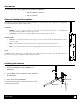
Card Installation The following illustrations depict installation into an H-Class printer, other model installations are similar. On some AClass models, the Network Card is installed upside-down. 1. Turn ‘Off’ the Power Switch and unplug the power cord from the AC Receptacle. Power Switch AC Receptacle 2. Remove the two Screws and Cover Plate from the rear of the printer. Screws Cover Plate 3. Slide the Wireless Card into the center slot of the printer.
Introduction These network cards can be equipped in the following configurations: Wired and Wireless Ethernet Wireless Ethernet External Hardware Descriptions The functions of the Interface Card’s external hardware are defined below. Depending on the configuration of your card some items may not be present. Connectors ANTENNA is used to connect an antenna or coaxial cable for RF reception and transmission via this Multimedia Communication Exchange (MMCX) Reverse Pin type connector.
Network Card Reset It is recommended that the printer’s communication settings be reset to factory defaults to avoid any conflicts in configuration. To reset the printer’s communication settings: 1. Turn on the printer and press the MENU BUTTON. 2. Using the DOWN BUTTON scroll to ‘COMMMUNICATIONS’ and press ENTER. 3. Using the DOWN BUTTON scroll to ‘NIC ADAPTER’ and press ENTER. 4. Using the DOWN BUTTON scroll to ‘SET FACTORY DEFAULTS’ and press ENTER. When prompted press the YES KEY.
Network Card Setup - Wireless (Infrastructure Mode) After a successful setup is made via a wired connection, the Wireless connection (if equipped) can now be configured in infrastructure mode using a static or DHCP issued IP address. 1. Open your web browser. Type in the IP Address of the printer. The Default IP is: 192.168.10.26. Note: If a different IP Address has been assigned to the printer, make sure to enter the correct IP Address. 2. A page similar to the right will appear: 3.
Network Card Setup - Wireless (Adhoc Mode) To configure the wireless card in Adhoc mode, you must configure your host computer to match the default settings of the printer. Your wireless network type must be Adhoc. Refer to your operating system’s or your wireless network card documentation for information on how to configure your computer. 1. Power on the printer. Enter the printer’s menu and navigate to the Communications/NIC Adapter/Quick Setup menu branch.
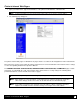
Printer’s Internal Web Pages 1. Open your web browser. Type in the IP Address of the printer. The Default IP is: 192.168.10.26. Note: If a different IP Address has been assigned to the printer, make sure to enter the correct IP Address. 2. The following page will appear: The printer’s internal web pages are divided into 15 pages that are accessible via the navigation bar on the left-hand side. Most of the items on these pages mimic the printer's internal menu.
GENERIC NETWORK CONFIGURATION Page NETWORK INTERFACE NETWORK INTERFACE Selects WIRED ETHERNET (802.3) or WIRELESS ETHERNET (WIFI 802.11) WIFI OPTION TYPE WIFI OPTION TYPE Selects which model of the communication card. This setting must match the model installed in the printer; DMXrfNet2 or DMXrfNet3. The model of the card is shown in the upper right hand corner of the cards mounting plate.
WIRED ETHERNET CONFIGURATION Page DHCP ENABLED/DISABLED Controls IP Address discovery, where: ENABLED: Broadcasts over the network to receive addresses from the responsible server at startup. Manual modifications to IP Address, Subnet Mask, or Gateway are not allowed; and, if no server is found, the specified static value will be used. DISABLED: Uses the stored static IP, Subnet Mask, and / or Gateway Address.
DMXrfNet3 Page (continued…) ADHOC CHANNEL ADHOC CHANNEL When Wireless Network Type is Ad Hoc, selects the channel used for communication. The two peer-to-peer devices must use the same channel. Range is 1 to 14 channels. Default channel is 1. WIFI REGION CODE WIFI REGION CODE Specifies the wireless channels allowed. The AP controls the channel used during Infrastructure mode. Default is US. SSID SSID Service Set Identifier that identifies the Module to connect to an AP.
Installing the Printer Driver The following screen shots are taken from Windows 2000, other Windows versions will be similar. 1 2 Start the Windows “Add Printer Wizard”. The following screen should appear, click ‘Next>’. Make sure that ‘Local Printer’ is selected and then click ‘Next’. 3 4 Select on ‘Create a new port:’ and then select ‘Standard TCP/IP Port’ from the drop down menu. Click ‘Next’ Click ‘Next’.
9 10 Insert the Accessories CD-Rom and click ‘Browse’. Browse to the “\DRIVERS\Seagull” folder on the CDROM, make sure the file “for 95, 98, me, 2000, and xp.inf” is selected and click ‘OK’. 11 12 Click ‘OK’. Choose your printer from the list and then click ‘Next’. 13 14 Name your printer in the ‘Printer name:’ field. Next select whether or not to set this printer as your default printer. Then Click ‘Next’. Select whether or not to share this printer on your network.
Wireless and Wired Ethernet Specifications The following list and table describes the key features and specifications of the wireless/wired card. 802.11b/g wireless LAN (Wi-Fi) standards-based technology Highly integrated module includes radio, baseband and MAC processor, and application processor Wired 10/100Mbs RJ-45 Ethernet port.