7A300019-2 Rev.
Contents General Precautions ...................................................................................................... 1 Safety ........................................................................................................................... 1 1 2 3 4 Getting Started ....................................................................................................... 2 1.1 Unpacking the Printer ..................................................................................
.2.2 5 6 Important Notes on Replacing Batteries ................................................ 16 4.3 Verifying Battery Charge State ........................................................................ 16 4.4 Battery and Safety Information ....................................................................... 17 4.5 Recycling Batteries ........................................................................................ 17 4.6 Troubleshooting ...........................................
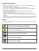
General Precautions • Before using this product be sure to read through this manual. After reading, please keep the manual in a safe place for future reference. • The information contained herein is subject to change without notice of any type. • Datamax-O’Neil is not responsible for any operational results regardless of missing information, errors or any misprinting in this manual. • Datamax-O’Neil is not responsible for problems created as a result of using options and consumables not approved by them.
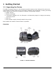
1 Getting Started 1.1 Unpacking the Printer The APEX 2 portable printer is a full-featured portable receipt printer designed for various job environments including field service, field sales, hospitality and restaurants, ticketing and many others where point of service receipts are required.
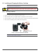
1.2 Installing and Charging the Battery Cartridge Note: One battery cartridge is included with the printer. Similar to a cordless phone battery, the printer’s battery must be charged before use. Datamax-O’Neil batteries must be cycled several times to achieve maximum capacity. To cycle a battery, fully charge it and then allow a full discharge through normal use. 1.2.1 Installing the Battery Note: Refer to the illustration below to install the battery pack in the printer.
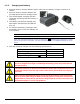
1.2.2 Charging the Battery Plug the battery charger adapter output cable into the battery charger connector as shown. Plug the battery charger adapter into the appropriate AC line voltage socket. The Yellow/Amber charging LED will illuminate indicating that the battery is charging. The battery will be fast charged and after about 180 minutes the LED will turn off. To remove the battery cartridge, open FIGURE 3: CHARGING THE BATTERY the battery door and tip the battery out of the printer.
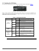
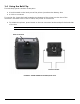
1.3 Reading the LED Status The illustration below points out the location of the LED indicators described in Table 1 FIGURE 4: LED INDICATOR LOCATIONS Table 1, below, details the LED indicator status. Refer to Figure 1 to locate the and push button switches and the AC adapter socket. Figure 4 provides the location of the status LEDs on the front of the printer.
1.4 Using the Belt Clip The belt loop system consists of two parts: A knob located on the back part of the printer just above the battery door A click-on connector To use the clip, insert the knob located at the bottom of the printer into the slot of the connector. Pull down until a click is heard; the printer is now secure To release the printer, press inward on the two connector latches and pull the knob clear of the slot.
2 Loading Supplies 2.1 Adding Paper or Labels The printer can print text, bar codes and graphics on thermal receipt paper. See “Supply Specifications” in Section 5.2 for the width, thickness requirements and approved vendors. Follow these steps to load printer paper. Press the Paper Door Release button; the door will open slightly. Open the door the rest of the way (as shown in Figure 6). Grip either side of the paper door and open – it will open 180 degrees.
While pressing the Paper Door Release button, close the paper door. Release the Paper Door Release button and press the printer door until fully closed Turn the printer ON by pressing the Power button and test the paper advance function by pressing the Paper Feed Button. Verify that the paper advances correctly. Note: Paper Supply Roll To prevent possible damage to the print mechanism, it is important to verify that the paper has not been fastened to the inside core in any way.
3 Using the Printer 3.1 Initial Power-Up and Self-Test Once the battery is charged and the paper is loaded an initial power-up self-test can be performed. Press the switch once. This turns printer on. The Green LED illuminates After approximately 20 seconds, if no instructions are sent to the printer, the printer will automatically turn off to conserve battery life. If the printer is set for Bluetooth communications (BT) mode the printer will stay on all the time.
3.2 Connecting the Printer The APEX 2 printer supports Serial RS232 and Bluetooth ™ as default configuration. IrDA or 802.11g communication is also available as an optional feature. Serial, IrDA and Bluetooth communication settings can be changed via a DIP switch located on the control card. The DIP switch is located inside the battery compartment. The illustration below indicates the location of this switch. Figure 10 shows the DIP switch selection.
3.2.3 Dip Switch Functions Table 2 shows the available dip switch settings. Table 2 – DIP Switch Setting Dip Switch Function Switch # Switch # 1& 2 Communication Interface SW 1 SW 2 RS232 OFF OFF Baud rate set by Dip switches 3,4 and 5 IrDA ON OFF Baud Rate can be negotiated up to the value specified through Dip switches 3,4 and 5 Bluetooth OFF ON 802.
3.3 Serial Communication The RS232C Interface signals for the APEX 2 Series printers are terminated on a 6 PIN RJ type data connector located on the side of the printer. Six connections are provided from the Serial Interface to the host computer. Table 3, below, lists the Serial Interface signals and pin outs on the RJ connector. The connector pin locations are shown in Figure 11. A minimum of two pin connections are required for operation, RXD – pin 3 and Common – pin 1.
3.4 Infrared Communications (IrDA) Dip Switch #1 must be in the position and Dip Switch #2 must be in the position. The printer can be powered ON by pressing the power switch. If no IrDA connection is made, the printer will automatically power down to a lower power level to conserve battery life. It will remain in a “sleep” mode until an IrDA connection is made, at which time the printer will “wake” and print the requested data.
Table 4 - Magnetic Card LED Indicator LED indicator State Status Green ON Ready/waiting for card to be swiped. OFF Good swipe - Card data read OR Card not ready to be swiped. Error reading card’s data. Red ON 3.7 Programming Information For programming information, please refer to the Developer’s Manual. Note: System Developers: Please refer to the APEX 2 developer’s manual for further details.
4 Printer Maintenance 4.1 Print Head Cleaning Instructions The print head and platen roller may need cleaning after printing a number of rolls of paper, when new supplies are loaded, or when voids in the printout are apparent. Do not use sharp objects to clean the print head. This may damage the printer and require service or repair Open the paper door by pressing the Paper Door Release Button as shown in Figure 6. The paper supply door will pop up. Remove the paper roll.
4.2.2 The fast-charge controller checks the battery’s voltage and temperature before the start of the fast recharge process. If the battery voltage or the temperature exceeds the fastcharge limits, the charger defaults to trickle charge at C/10 or 70mA rate. Optional external battery chargers are available for Datamax-O’Neil batteries. Refer to Section 4.7 “Printer Supplies” for detailed information.
As long as the amber LED is ON, the battery is accepting a charge and the charging circuit is OK. At the end of a 180 minute charge cycle the LED will switch off. 4.4 Battery and Safety Information The printer is powered by a 7.4V Li-Ion battery cartridge. Charging time for the printer is approximately 3.0 hours. Remove the battery from the printer before storing the printer for long periods of time. The battery storage temperature is 40°F to 104°F (4°C to 40°C).
4.
4.7 Printer Supplies Part Number Description 78728S1-3 78728S1R-3 78728S1-2 78728S1R-2 151133 756983 APEX 2, Standard with Class 2 BT APEX 2, Standard with Class 2 BT and MCR Apex 2 with 802.11b/g Apex 2 with 802.
20
5 Specifications 5.1 Printer Specifications Height: Width: Length: Weight: w/battery & supply Shipping weight: Power: Operating Temp. Limits: Storage Temp. Limits: Operating Humidity Limits: Storage Humidity Limits: Print head: Printing Method: Print Speed: Supported Fonts: (Bitmap) Supported Bar Codes: Memory: Charging Time: Communications: Print Ratio: 2.7 inches (68mm) 4.2inches (107mm) 5.4 inches (138mm) 1 lb (465g) 2.8 lbs. (1.31 kg) 7.
5.3 Regulatory Notes 5.3.1 FCC Part 15 Class B This equipment has been tested and found to comply with the limits for a Class B digital device, pursuant to Part 15 of the FCC rules. These limits are designed to provide reasonable protection against harmful interference in a residential installation. This equipment generates, uses, and can radiate radio frequency energy and, if not installed and used in accordance with the instructions, may cause harmful interference to radio communications.
6 Customer Support Datamax-O'Neil Americas Orlando, FL USA Monday - Friday 8:00am - 6:00pm EST Tel: 407-523-5540 Fax: 407-523-5542 tech_support@datamax-oneil.com Datamax-O’Neil EMEA Valence France Monday - Friday 0830 - 1700 GMT Tel: + 33 (0) 4 75 75 63 00 Fax: +33 (0) 4 75 82 98 38 eurotech@datamaxcorp.com Datamax-O'Neil Asia-Pacific Singapore Monday - Friday 0830 - 1730 Tel: +65 6505 2250 Fax: +65 6769 8135 tsaspa@datamax-oneil.