
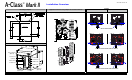
Installation Instruction Manual
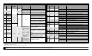

GPI/O Port A Overview
Pin Signal
Signal
Direction
[1]
Jumper Position Function / Description
Installed Printer chassis is used.
1
Ground
JMP 8
Removed Ground externally supplied.
Installed Printer voltage used (.5 amp max)
[4]
2 +5 VDC
N/A
JMP 9
Removed +5VDC externally supplied.
3
Start Of
Print
[2]
SOP signal; programmable
[3]
4 Slew Label
Advances media until HIGH and then,
if not Continuous, positions at TOF.
5
Toggle /
Pause
Pauses the printer when LOW.
6 Reprint
Input
Reprints the last label; and, if always
LOW, results in non-stop printing.
7 +24 VDC Printer +24 VDC (1.5 amp maximum)
8 Ground
N/A
N/A N/A
Printer chassis.
9 Ribbon Low
Programmable
[1]
; warning LOW
DIAMETER condition.
10
Service
Required
Evoked upon Fault
[1]
; Active LOW.
11
End Of
Print
Programmable
[1]
; EOP process end.
12 Media Out
Evoked when Out of Stock; active
LOW.
13 Ribbon Out
Evoked when Out of Ribbon; active
LOW.
14 Data Ready
Evoked if a label awaits; after the
SOP, printing begins. Active LOW.
15
Option
Fault
Output JMP 1
When inactive,
outputs pulled up to
a voltage determined
by jumper settings,
where:
Pins 1-2 = +5VDC;
Pins 2-3 = 24VDC;
or,
None = Common
external voltage
(not to exceed
+30VDC) via
external pull-ups
(providing a 20K
ohm feedback thru
any two outputs).
Evoked during a Linear Scanner or
RFID fault; active LOW.
GPI/O Port B Overview
Pin
Signal &
Direction
[1]
Jumper Position Function / Description
Installed Printer voltage used (.5 amp max)
[4]
1
+5 VDC JMP 11
Removed +5VDC externally supplied.
2 Input 6 N/A N/A Programmed function.
3 Input 3 N/A N/A Programmed function.
Installed: Pins 1-2 Programmed function pulled-up to +5VDC.
Installed: Pins 2-3 Programmed function pulled-up to +24VDC. 4 Output 6 JMP 7
Removed External source and pull-ups, not to exceed 30VDC.
Installed: Pins 1-2 Programmed function pulled-up to +5VDC.
Installed: Pins 2-3 Programmed function pulled-up to +24VDC.
5 Output 3 JMP 4
Removed External source and pull-ups, not to exceed +30VDC.
Installed Printer chassis is used.
6 Ground JMP 10
Removed Ground externally supplied.
7 Input 5 N/A N/A Programmed function.
8 Input 2 N/A N/A Programmed function.
Installed: Pins 1-2 Programmed function pulled-up to +5VDC.
Installed: Pins 2-3 Programmed function pulled-up to +24VDC.
9 Output 5 JMP 6
Removed External source and pull-ups, not to exceed +30VDC.
Installed: Pins 1-2 Programmed function pulled-up to +5VDC.
Installed: Pins 2-3 Programmed function pulled-up to +24VDC.
10 Output 2 JMP 3
Removed External source and pull-ups, not to exceed +30VDC.
11 +24 VDC N/A N/A Printer +24 VDC (1.5 amp max).
12 Input 4 N/A N/A Programmed function.
13 Input 1 N/A N/A Programmed function.
Installed: Pins 1-2 Programmed function pulled-up to +5VDC.
Installed: Pins 2-3 Programmed function pulled-up to +24VDC.
14 Output 4 JMP 5
Removed External source and pull-ups, not to exceed +30VDC.
Installed: Pins 1-2 Programmed function pulled-up to +5VDC.
Installed: Pins 2-3 Programmed function pulled-up to +24VDC.
15 Output 1 JMP 2
Removed External source and pull-ups, not to exceed +30VDC.
[1]
Signal directions given relative to the printer.
[2]
If active with no current print job, “WAITING FOR DATA” will be displayed. Specifying a quantity of 9999 while keeping this signal ON will cause non-stop label printing, except in single label “Imaging Mode” which will cause the printer to stop between labels.
[3]
See PRINTER OPTIONS / GPIO PORT.
[4]
Drawing more than 0.5 amps can cause unreliable printer operation.
WARNING: Failure to properly configure the GPIO Port jumper settings may result in damage to the printer and / or applicator.