
Quick Reference Guide
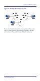

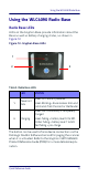
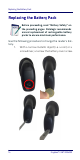
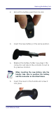

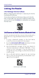
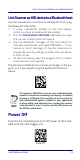
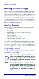
Table Of Contents
- Gryphon™ I GBT/GM4500
- Table of Contents
- END USER SOFTWARE LICENSE AGREEMENT
- About the Scanner
- Setting Up the Reader
- Reader, Cradle and LEDs Description
- Connecting the Base Station
- System and Network Layouts
- Using the GBT/GM4500 Scanner
- Using the WLC4090 Radio Base
- Replacing the Battery Pack
- Using the Gryphon™ I GBT/GM4500
- Linking the Reader
- Link Scanner as Serial Device to a Bluetooth Host
- Link Scanner as HID device to a Bluetooth host
- Power Off
- Selecting the Interface Type
- Programming
- Reading Parameters
- Operating Modes
- Technical Features
- LED and Beeper Indications
- Troubleshooting
- Ergonomic Recommendations
- Cleaning Procedure
- Support Through the Website
- Charging the Batteries
- Datalogic Limited Factory Warranty

Using the WLC4090 Radio Base
Quick Reference Guide 13
Using the WLC4090 Radio Base
Radio Base LEDs
LEDs on the Gryphon Base provide information about the
Base as well as battery charging status, as shown in
Figure 12.
Figure 12- Gryphon Base LEDs
Table 2. Radio Base LEDs
The button can be used to force device connection via the
Datalogic Aladdin Software tool and for paging the scanner
when it is activated. Refer to the Gryphon I GBT/GM4500
Product Reference Guide (PRG) for a more detailed expla-
nation.
LED STATUS
1
Power on /
Data
Green On = Base is powered
Green Blinking = Base receives data and
commands from the Host or the Reader.
2
Charging
Green ON = the battery is completely
charged
Green fading = battery level 51 to 99%
Amber fading = battery level 1 to 50%
Red fading = pre-charge
1
2
2