PowerScan® 7000 2D Imager Quick Reference Guide
Datalogic Scanning, Inc. 959 Terry Street Eugene, Oregon 97402 Telephone: (541) 683-5700 Fax: (541) 345-7140 An Unpublished Work - All rights reserved. No part of the contents of this documentation or the procedures described therein may be reproduced or transmitted in any form or by any means without prior written permission of Datalogic Scanning, Inc. or its subsidiaries or affiliates ("Datalogic" or “Datalogic Scanning”).
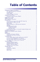
Table of Contents Statement of Agency Compliance ...........................................................iii FCC Class B Compliance Statement ..................................................iii Canadian Notice ............................................................................iii Power Supply ................................................................................iii Solids and Water Protection ............................................................iii Software Product Policy ....
NOTES ii PowerScan® 7000 2D Imager
Statement of Agency Compliance This device complies with part 15 of the FCC Rules. Operation is subject to the following two conditions: (1) this device may not cause harmful interference, and (2) this device must accept any interference received, including interference that may cause undesired operation. FCC Class B Compliance Statement This equipment has been tested and found to comply with the limits for a Class B digital device pursuant to part 15 of the FCC Rules.
Datalogic Scanning, Inc. POWERSCAN® END USER LICENSE AGREEMENT Notice to End User: The Datalogic Product you have acquired contains embedded Software, which is integral to the product’s operation. This Software is being provided to you under license, subject to the terms and conditions of this Agreement. If you use the Datalogic Product, you will be deemed to have accepted the terms and conditions of this Agreement.
Statement of Agency Compliance 5.2 5.3 End User shall not disclose, provide, or otherwise make available the Proprietary Information of Datalogic or its third party licensors to any person other than End User’s authorized employees or agents who are under confidentiality agreement, and End User shall not use the Proprietary Information other than in conjunction with use of the Datalogic Product exclusively for End User’s internal business purposes.
and shall return to Datalogic or destroy all non-embedded software covered by this Agreement, and shall furnish Datalogic with a certificate of compliance with this provision signed by an officer or authorized representative of End User. For embedded software, End User agrees to sign a waiver prepared by Datalogic concerning further use of the embedded Software.
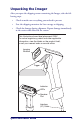
Unpacking the Imager After you open the shipping carton containing the Imager, take the following steps: • Check to make sure everything you ordered is present. • Save the shipping container for later storage or shipping. • Check for damage during shipment. Report damage immediately to the carrier who delivered the carton. This illustration shows label placement ONLY.
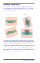
Reading Techniques The imager has a viewfinder that projects a bright green aiming beam that corresponds to the imager’s horizontal field of view. The aiming beam should be centered over the bar code, but it can be positioned in any direction for a good read. Linear bar code 2D Matrix The aiming beam is smaller when the imager is closer to the code and larger when it is farther from the code. Symbologies with smaller bars or elements (mil size) should be read closer to the unit.
LED and Beeper Indications LED and Beeper Indications The imager is equipped with a beeper (speaker) and two indicator LEDs; one green and one yellow. These indicators “beep” or flash when certain actions take place: NOTE Some LED and Beeper indications are user-configurable for volume, pitch, quantity, duration, enable/disable, etc. Those listed in the following table assume the feature is enabled. See the Product Reference Guide (PRG) for detailed programming information.
Plug and Play Plug and Play bar codes provide instant imager set up for commonly used interfaces. After you scan one of the codes, power cycle the host terminal to have the interface in effect. NOTE Connecting the imager with an RS-232 Serial Port These instructions are for use with the RS-232 cable. This includes both Power Off the Terminal (P.O.T.) and external power. NOTE 1. Turn off power to the terminal/computer. 2. Connect the appropriate interface cable to the imager.
Plug and Play 3. Plug the serial connector into the serial port on your computer. Tighten the two screws to secure the connector to the port. 4. If the terminal does not support Power Off the Terminal (P.O.T.) connections plug the power supply into the host connector and the AC outlet. 5. Once the imager has been fully connected, power up the computer. All communication parameters between the imager and terminal must match for correct data transfer through the serial port using RS-232 protocol.
2. The imager beeps. 3. Verify imager operation by scanning the part number bar code from the back cover of this manual. NOTE The following USB “Plug and Play” codes are supported on specific models. Refer to the Product Reference Guide to determine if this interface applies to your unit. For additional USB programming and technical information, visit the website listed on the back cover of this manual.
Plug and Play Each bar code above also programs the following suffixes for each symbology: Symbology EAN-8 EAN-13 UPC-A UPC-E Code 39 Interleaved 2 of 5 Code 128 NOTE Suffix 0C 16 0D 0A 00 0A 0B 00 0D 0B 00 18 0B The following USB “Plug and Play” codes (USB Keyboard - PC, USB Keyboard - Mac, and USB HID) are supported on specific imager models. Check your model type to determine if this interface applies to your unit.
USB HID Scan the following code to program the imager for USB HID bar code imagers. Scanning this code changes the terminal ID to 131. USB HID Bar Code imager USB COM Port Emulation Scan the following code to program the imager to emulate a regular RS232-based COM port. If you are using a Microsoft® Windows® PC, you will need to download a driver from the website listed on the back cover of this manual. The driver will use the next available COM port number.
Plug and Play ACK/NAK Mode On * Off Reference the Product Reference Guide (PRG) for more information about keyboard support. NOTE Connecting the imager in Universal Keyboard Wedge mode The Universal Keyboard Wedge (UKBW) model allows an RS-232 transmission or Keyboard Wedge mode according to the type of cable connected. Contact Datalogic or your dealer for cable and/or power supply part numbers. 1. Turn off power to the terminal/computer. 2. Connect the keyboard wedge interface cable to the imager.
3. Connect one end of the Y cable to the keyboard cable and the other to the keyboard port on the host/computer. Cable Connector Retainer Boss K ey Captive Screws bo ard 4. Scan the following bar code to program the imager for the UKBW interface. ~ p Universal a p 2 Keyboard 3 2 ; Wedge 2 3 (UKBW) 2 C T Interface S 1 ³ .
Resetting the Standard Product Defaults Resetting the Standard Product Defaults If programming settings for your scanner are in an unknown condition, factory settings can be restored by scanning the “Standard Product Default Settings” bar code below. A listing of factory default settings is available in the PRG. Settings can vary, depending upon the interface type. Standard Product Default Settings Repairs Repairs and/or upgrades are not to be performed on this product.
The imager’s housing may also be cleaned the same way. CAUTION Do not submerge the imager in water. Do not use abrasive wipes or tissues on the imager’s window – abrasive wipes may scratch the window. Never use solvents (e.g., acetone, benzene, ether, or phenol-based agents) on the housing or window – solvents may damage the finish or the window. Inspecting Cords and Connectors Inspect the imager’s interface cable and connector for wear or other signs of damage.
Troubleshooting • Are enabled in the imager (see the Product Reference Guide for more about symbologies). Is the bar code displayed but not entered? The bar code is displayed on the host device correctly, but you still have to press a key to enter it (the Enter/Return or Tab key, for example). You need to program a suffix. Programming a suffix enables the imager to output the bar code data plus the key you need (such as “CR”) to enter the data into your application.
2. If the imager still can’t read the sample bar codes, scan the “All Symbologies” setting from the Product Reference Guide. If you aren’t sure what programming options have been set in the imager, or if you want the factory default settings restored, see Resetting the Standard Product Defaults on page 11. Technical Support Datalogic Website Support The Datalogic website (www.scanning.datalogic.com) is the complete source for technical support and information for Datalogic products.
Standard Warranty Standard Warranty Datalogic warrants to Customer that Datalogic's products will be free from defects in materials and workmanship for a period of three years from product shipment. In order to obtain service under this Warranty, Customer must notify Datalogic of the claimed defect before the expiration of the Warranty period and obtain from Datalogic a return authorization number for return of the product to designated Datalogic service center.
Limitations of Liability Datalogic repair or replacement of defective product as set forth above is the customer's sole and exclusive remedy on account of claims of breach of warranty or product defect. Under no circumstances will Datalogic be liable to customer or any third party for any lost profits, or any incidental, consequential indirect, special or contingent damages regardless of whether Datalogic had advance notice of the possibility of such damages.
Standard Warranty NOTES Quick Reference Guide 17
NOTES 18 PowerScan® 7000 2D
DECLARATION OF CONFORMITY Datalogic hereby declares that the Equipment specified below has been tested and found compliant to the following Directives and Standards: Directives: EMC 89/336/EEC Low Voltage 73/23/EEC Standards: EN 55022-B:A2/2003 - Generic Emissions CISPR 22-B:2005 - Generic Emissions EN 55024/A2:2001 - Generic Immunity – ITE EN 60950-1:2001 - ITE Safety EN 60825-1/A2:2002 - Laser Safety EN61000-3-2:2000 – Harmonic Current EN61000-3-2:2001 - Voltage Fluctuation/Flicker Equipment Type: Barco
Australia Japan Datalogic Scanning Pty Ltd Datalogic Scanning KK North Ryde, Australia Shinagawa, Tokyo, Japan Telephone: [61] (2) 9870 3200 Telephone: 81 (0)3 3491 6761 Fax: [61] (2) 9878 8688 Fax: 81 (0)3 3491 6656 France and Benelux Latin America Datalogic Scanning Sarl Datalogic Scanning, Inc LES ULIS Cedex, France Miami, Florida, USA Telephone: [33].01.64.86.71.00 Telephone: (305) 591-3222 Fax: [33].01.64 46.72.