
Operation Manual
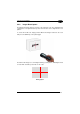
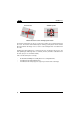
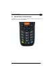
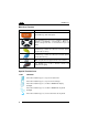

Table Of Contents
- CONTENTS
- REFERENCES
- GENERAL VIEW
- 1 INTRODUCTION
- 2 BATTERIES AND MAINTENANCE
- 3 CONNECTIONS
- 4 USE AND FUNCTIONING
- 4.1 STARTUP
- 4.2 DATA CAPTURE
- 4.3 DESCRIPTION OF THE KEYBOARDS
- 4.4 STATUS INDICATORS
- 4.5 CONTROL PANEL
- 4.6 CONNECTING TO OTHER COMPUTERS
- 4.7 BACKUP DIRECTORY FILE MANAGEMENT
- 4.8 DATALOGIC FIRMWARE UTILITY
- 4.9 DATALOGIC CONFIGURATION UTILITY
- 4.10 DATALOGIC DESKTOP UTILITY
- 4.11 APPSELECTOR (APPLICATION SELECTOR)
- 4.12 LOCKED WEB BROWSER
- 5 TECHNICAL FEATURES
- 6 TEST CODES
- REGULATORY INFORMATION
- GLOSSARY
- INDEX
- DECLARATION OF CONFORMITY
1 MEMOR™ X3
42
4
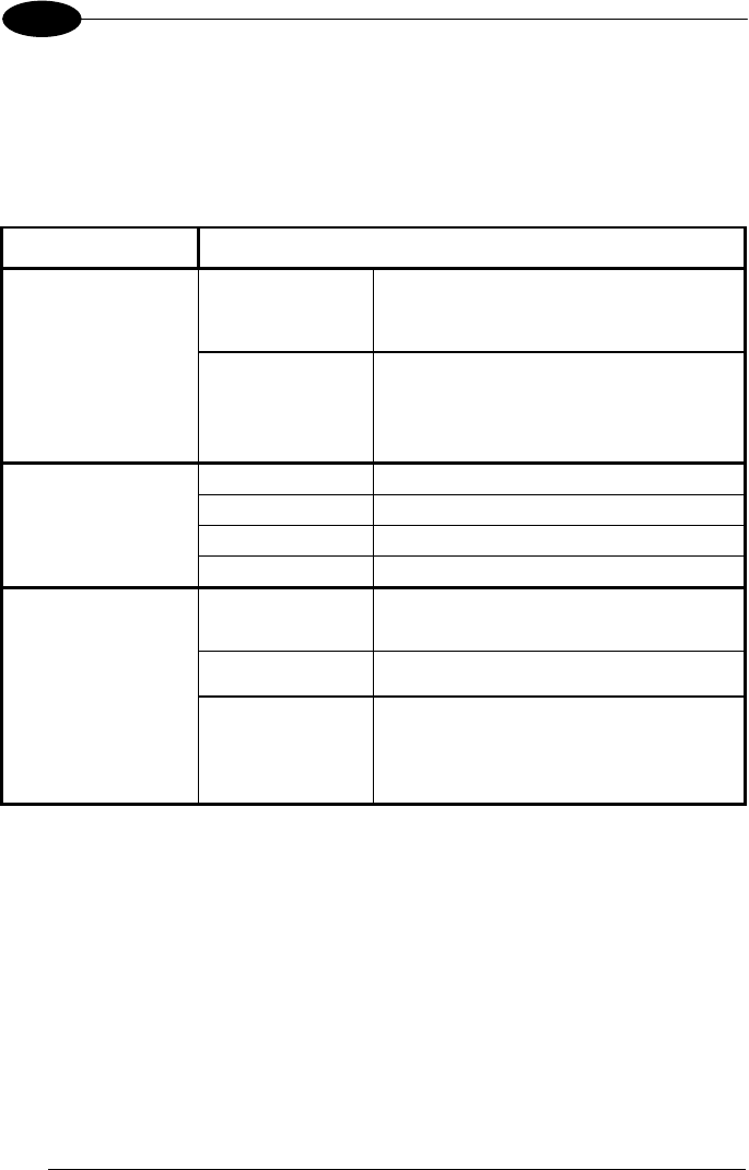
4.4 STATUS INDICATORS
4.4.1 LED Status
The Memor X3 provides three different LEDs signaling the mobile computer status.
LED STATUS
Good Read and
General Purpose
(left side)
Green
Scanning LED is ON, showing a good
decode.
Red
Scanning LED is ON from the time the
user hits the scan button (Trigger) until
the bar code is decoded.
Keyboard Status
(center)
Off
Keyboard in primary mode.
Yellow solid
Yellow alternate key mode.
Blue solid
Blue alternate key mode
Pink
CapsLock enabled.
Charging Status
(right side)
Green
It is constant once the charging process
has been completed (full charge).
Red It is constant while charging.
Red Blinking
It blinks in case of charge fault.