
Specifications


RAPID CONFIGURATION
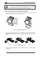
1
1 RAPID CONFIGURATION
STEP 1 – CONNECTING THE SYSTEM
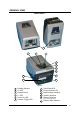
To connect the system in a Stand Alone configuration, you need the hardware indicated in
Figure 1. In this layout the data is transmitted to the Host on the main serial interface. The
RS232 auxiliary interface can be used for reader configuration by connecting a laptop
computer running VisiSet™.
When One Shot or Phase Mode Operating mode is used, the reader is activated by an
External Trigger (photoelectric sensor) when the object enters its reading zone.
Matrix-2000™
CBO
X
-100
Terminal
P.S.*
Main Interface
Local Host
PG 6000
* External Trigger or Presence Sensor (for On Shot or Phase Mode)
Figure 1 – Matrix-2000™ in Stand Alone Layout
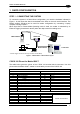
C-BOX 100 Pinout for Matrix-2000™
The table below gives the pinout of the C-BOX 100 terminal block connectors. Use this
pinout when the Matrix-2000™ reader is connected by means of the C-BOX 100:
C-BOX 100 Terminal Block Connectors
Power Outputs
1, 3, 5 VS 21 OUT 1+
2, 4, 6 GND 22 OUT 1-
7, 8 EARTH GROUND 23 OUT 2+
20, 40 Reserved 24 OUT 2-
Inputs
25 OUT 3+
27 EXT TRIG A (polarity insensitive) 26 OUT 3-
28 EXT TRIG B (polarity insensitive)
Auxiliary Interface
29 IN 2A (polarity insensitive) 35 TX AUX
30 IN 2B (polarity insensitive) 37 RX AUX
31, 33 NC 38,39 GND
32, 34 NC
36 NC
Main Interface
RS232 RS485 Full-Duplex RS485 Half-Duplex 20 mA C.L. (with INT-30 only)
11, 15 TX 232 TX 485+ RTX 485+
12, 16 RTS 232 TX 485- RTX 485-
17 RX 232 RX 485+
18 CTS 232 RX 485-
10, 14, 19 GND_ISO GND_ISO GND_ISO
9, 13 RS485 Cable Shield RS485 Cable Shield
see INT-30 instructions
1