
Specifications


INSTALLATION
3
3.3.3 Auxiliary RS232 Interface
The RS232 auxiliary interface is available for Point-to-Point, Pass Through or Master/Slave
connections. When it is connected to the host computer it allows both transmission of code
data and reader configuration by VisiSet™.
Its communication parameters (baud rate, data bits, etc.) can be defined by the user.
For more details refer to the "Communication" folder in the VisiSet™ Help On Line.
The auxiliary interface is available on both D-sub connectors with the following pinouts:
9-Pin 25-Pin Name Function
2 21 TXAUX Transmitted data
3 20 RXAUX Received data
5 23 GND Ground
MATRIX
21
TXAU
X
RXAU
X
20
USER INTERFACE
RXD
TXD
23
GND
Ground
Earth
Ground
1
SHIELD
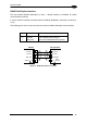
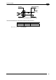
Figure 45 - RS232 Auxiliary Interface Connections Using 25-pin Connector
MATRIX
2
TXAU
X
RXAU
X
3
USER INTERFACE
RXD
TXD
5
GND
Ground
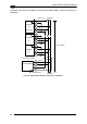
Figure 46 - RS232 Auxiliary Interface Connections Using 9-pin Connector
When the auxiliary interface is permanently connected as part of the system cabling, it is
recommended to use the 25-pin connector and connect the cable shield as shown in Figure
45.
CAUTION
Avoid simultaneous connection to 25-pin and 9-pin signals of the auxiliary
RS232 interface.
CAUTION
If Matrix-2000™ is connected to a C-BOX 3x0/4x0 through its 25-pin
connector, then the Matrix-2000™ 9-pin Auxiliary port connector cannot be
used for communication (i.e. configuration through VisiSet™). In this case
use the Auxiliary port 9-pin connector inside the C-BOX 3x0/4x0.
35