
Specifications

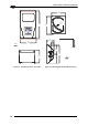


INSTALLATION
3
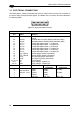
There is also a separate 9-pin female D-sub connector for the Auxiliary port connection with
the following pinout:
5
1
9
6
Figure 37 - 9-pin female D-Sub Connector
9-pin female D-sub connector pinout
Pin Name Function
2 TXAUX Transmitted data of auxiliary RS232
3 RXAUX Received data of auxiliary RS232
5 GND Reference GND of auxiliary RS232
1,4,6,7,8,9 N.C. Not connected
CAUTION
If Matrix-2000™ is connected to a C-BOX 3x0/4x0 through its 25-pin
connector, then the Matrix-2000™ 9-pin Auxiliary port connector cannot be
used for communication (i.e. configuration through VisiSet™). In this case
use the Auxiliary port 9-pin connector inside the C-BOX 3x0/4x0.
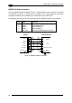
In Matrix-21XX models a RJ45 Modular Jack is provided for Ethernet connection. This
interface and the connector pinout (see the following table) are IEEE 802.3 10 BaseT and
IEEE 802.3u 100 BaseTx compliant.
1
8
Figure 38 - RJ45 Modular Jack
RJ45 modular jack pinout
Pin Name Function
1 TX + Transmitted data (+)
2 TX - Transmitted data (-)
3 RX + Received data (+)
6 RX - Received data (-)
4,5,7,8 N.C. Not connected
In order to meet EMC requirements:
• connect the reader chassis to the plant earth ground by means of a flat copper braid
shorter than 100 mm;
• connect the main interface cable shield to pin 1 of the 25-pin connector;
• use two clip-on ferrite sleeves (type Stewart 28A2029-0A0 or equivalent) on the main
interface cable near the reader 25-pin connector;
• connect the Ethernet interface cable shield to reader chassis (for Matrix-21XX only)
27