MATRIX-2000™ Reference Manual
Datalogic Automation S.r.l. Via S. Vitalino 13 40012 - Lippo di Calderara di Reno Bologna - Italy Matrix-2000™ Reference Manual Ed.: 05/2007 ALL RIGHTS RESERVED Datalogic reserves the right to make modifications and improvements without prior notification. Datalogic shall not be liable for technical or editorial errors or omissions contained herein, nor for incidental or consequential damages resulting from the use of this material.
CONTENTS REFERENCES ............................................................................................................. v Conventions.................................................................................................................. v Reference Documentation ............................................................................................ v Service and Support ..................................................................................................... v Patents..
.2 4.3 4.3.1 4.4 4.4.1 4.4.2 4.5 4.6 Installing VisiSet™...................................................................................................... 50 Startup ........................................................................................................................ 51 VisiSet™ Options........................................................................................................ 52 Configuration ..............................................................................
REFERENCES CONVENTIONS This manual uses the following conventions: "User" refers to anyone using a Matrix-2000™ reader. "Reader" refers to the Matrix-2000™ reader. "You" refers to the System Administrator or Technical Support person using this manual to install, configure, operate, maintain or troubleshoot a Matrix-2000™ reader.
COMPLIANCE For installation, use and maintenance it is not necessary to open the reader.
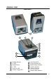
GENERAL VIEW Matrix-2000™ 1 2 3 4 5 6 7 8 12 9 11 10 Figure A 1 2 3 4 5 6 Reading Window F2 LED Keypad button F1 LED Power On LED External Trigger LED 7 8 9 10 11 Good Read LED Communication LED Main/Auxiliary Interface Auxiliary Interface Ethernet Interface (for 21XX models only) 12 Ethernet MAC Address vii
viii
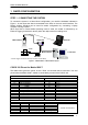
RAPID CONFIGURATION 1 1 RAPID CONFIGURATION STEP 1 – CONNECTING THE SYSTEM To connect the system in a Stand Alone configuration, you need the hardware indicated in Figure 1. In this layout the data is transmitted to the Host on the main serial interface. The RS232 auxiliary interface can be used for reader configuration by connecting a laptop computer running VisiSet™.
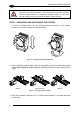
Matrix-2000™ Reference Manual 1 CAUTION If Matrix-2000™ is connected to a C-BOX 3x0/4x0 through its 25-pin connector, then the Matrix-2000™ 9-pin Auxiliary port connector cannot be used for communication (i.e. configuration through VisiSet™). In this case use the Auxiliary port 9-pin connector inside the C-BOX 3x0/4x0. STEP 2 – MOUNTING AND POSITIONING THE SYSTEM 1. To mount the Matrix-2000™, use the mounting bracket to obtain the most suitable position for the reader as shown in the figures below.
RAPID CONFIGURATION 1 STEP 3 – AUTOLEARNING CONFIGURATION An autolearning procedure is available to reduce installation time.
Matrix-2000™ Reference Manual 1 NOTE Autolearning configuration parameters can be saved to temporary memory only by selecting the "Autolearning Setup>Store Memory" parameter in VisiSet™. The Autolearning function on the keypad button can also be disabled by the user via VisiSet™. Auto Learn (F2) green Figure 4 – Auto Learn Function Repeat the procedure if needed, to program different code symbologies, however you must present only one code at a time to the reader.
RAPID CONFIGURATION 1 To cancel the Positioning function, press and hold the keypad button at any time during the procedure: the F1 LED will stop blinking and Matrix-2000™ will emit a long low pitched beep. Positioning (F1) yellow Figure 5 – Positioning Function Restore Default (Optional) At any time you can use the Restore Default procedure to return the reader to the factory default settings. 1.
Matrix-2000™ Reference Manual 1 STEP 4 – INSTALLING VISISET™ CONFIGURATION PROGRAM VisiSet™ is a Datalogic reader configuration tool providing several important advantages: • Autolearning Wizard for new users; • Defined configuration directly stored in the reader; • Communication protocol independent from the physical interface allowing to consider the reader as a remote object to be configured and monitored.
RAPID CONFIGURATION 1 The Autolearning Wizard option is advised for rapid configuration or for new users. It allows reader configuration in a few easy steps. 1. Select the Autolearning Wizard button from the Main menu. 2. Place the desired code in front of the reader at the correct reading distance (depending on the model, see the Reading Features table in the Appendix of this Quick Reference Guide). 3. Press the "Positioning" button.
Matrix-2000™ Reference Manual 1 The reader flashes once acquiring the image and auto determines the best exposure and gain settings. If the code symbology is enabled by default, the code will also be decoded. 5. If the code symbology is not enabled by default, select a Code Setting Mode choice and press the "Code Setting" button. The Autolearning Result section of the Autolearning Wizard window shows the parameter settings and the code type results. 6.
RAPID CONFIGURATION 1 ADVANCED READER CONFIGURATION For further details on advanced product configuration, refer to the VisiSet™ Help On-Line. The following are alternative or advanced reader configuration methods: Advanced Configuration Using VisiSet™ Advanced configuration can be performed through the VisiSet™ program by selecting Device> Get Configuration From Temporary Memory to open the Parameter Setup window in off-line mode.
2 Matrix-2000™ Reference Manual 2 GENERAL FEATURES 2.1 INTRODUCTION Matrix-2000™ is a Datalogic compact 2D reader designed and produced to be a high performance affordable solution for both linear and two-dimensional code reading applications. Matrix-2000™ has been developed for use in numerous applications, including PCB and electronic manufacturing, packaging lines, small item tracking, analysis machines and document handling systems, and can also be easily integrated into a wide range of OEM solutions.
GENERAL FEATURES 2 2.
2 Matrix-2000™ Reference Manual The following indicators are located on the top of the reader: PWR red LED indicates that the reader is connected to the power supply (see Figure A, 5); TRIG yellow LED indicates external trigger activity (Figure A, 6); for details refer to par 3.3.5; READ red LED signals successful code decoding (Figure A, 7). It is also used to signal successful startup. At power on this LED turns on and after a few seconds turns off.
GENERAL FEATURES 2 2.3 MODEL DESCRIPTION The Matrix-2000™ reader is available in different versions according to the following characteristics: MATRIX - 2XXX-X Device Connectivity Optics Image Sensor Other Options 0 = RS232/RS485 + RS232 1 = RS232/RS485 + RS232+ Ethernet 1 = Ultra High Density (UHD) 2 = High Density (HD) 3 = Standard Density (STD) 4 = Low Density (LD) 5 = Medium Range (MR) 6 = Long Range (LR) 1 = VGA CCD 5 = SXGA CMOS R = 90° Reading Window 2.4 ACCESSORIES Order No.
Matrix-2000™ Reference Manual 2 2.5 APPLICATION EXAMPLES Matrix-2000™ is profitably used in the omnidirectional reading of 2D, stacked, linear and postal codes. The powerful LED illuminator, the Matrix 2XX1 60 fps CCD sensor and the 400 MHz CPU allow the decoding of fast moving codes (over 6.0 m/s) on industrial printing lines (see Figure 10) and in automated document handling and mail processing systems (see Figure 11).
GENERAL FEATURES 2 Matrix-2000™ assures the reading of deformed and / or overprinted codes, even though damaged or printed on high reflective surfaces (see Figures 12,13,14).
2 Matrix-2000™ Reference Manual Figure 17 - Dot Peening Marking on Metal Surface with Multi-dot per Code Element Figure 18 - Directly Marked Dot Matrix Code Characterized by Outstanding Separation Distance between Adjacent Code Elements Figure 19 - DataMatrix Code Directly Marked on PCB Surface by Using Laser Etching Technology Figure 20 - Dot Matrix Code Directly Marked on PCB Copper Pad by Using Ink-Jet Technology 16
GENERAL FEATURES 2.5.1 2 External Lighting Systems In some direct part marking applications best reading results are obtained by using an external lighting system. A series of accessory illuminators are available which cover a variety of applications.
2 Matrix-2000™ Reference Manual The LT-210 Spot Lighting System provides a high intensity light source designed for the following applications: • with uneven, noisy and scratched surfaces • where dot peening or laser etching codes are directly marked onto metal surfaces or PCBs and need to be highlighted. Here the use of more than one Spot Light can remove any shadowing effect. • in the presence of highly reflective surfaces (metal, glass, etc.) causing direct reflections.
GENERAL FEATURES 2 The LT-314 45° Dark Field Ring Lighting System is designed for reading codes produced by Dot Peening or Laser Etching on flat, reflective parts. Figure 25 - LT-314 45° Dark Field Ring Lighting System The LT-316 60° Dark Field Ring Lighting System is designed for reading codes produced by Dot Peening (especially by a 120° stylus) or Laser Etching on flat, reflective parts.
2 Matrix-2000™ Reference Manual The LT-410 Coaxial Lighting System is an axial diffuse illuminator designed for reading codes produced by Dot Peening or Laser Etching on flat parts having a matte, specular or mixed surface reflectivity. Figure 27 - LT-410 Coaxial Lighting System The LT-510 Mini Dome Lighting System is a diffuse mini dome light designed for reading printed label or Direct Marking codes on small parts with a curved or specular surface.
GENERAL FEATURES 2 The LT-511 Dome Lighting System is a diffuse dome light designed for reading printed label or Direct Marking codes on parts with a curved surface. Figure 29 - LT-511 Dome Lighting System The LT-630 Four Bar Lighting System is designed for Code verification applications according to ISO/IEC 15415 or ISO/IEC 15416 specifications.
Matrix-2000™ Reference Manual 3 3 INSTALLATION 3.1 PACKAGE CONTENTS Verify that the Matrix-2000™ reader and all the parts supplied with the equipment are present and intact when opening the packaging; the list of parts includes: Matrix-2000™ reader Quick Reference Guide Test chart Matrix family CD-ROM Auxiliary port connector cover Mounting kit • Mounting screws and washers (4 ea.
INSTALLATION 3 3.2 MECHANICAL INSTALLATION Matrix-2000™ can be installed to operate in different positions. The eight screw holes (M4 x 5) on the body of the reader are for mechanical fixture (Figure 32). The diagram below gives the overall dimensions of the reader and may be used for its installation. Refer to paragraph 3.5 for correct positioning. 57 [2.24] = 73 [2.87] 57 [2.24] 18.1 [0.71] M4 x 5 n°4 57 [2.24] 4 [0.16] mm [inch] M4 x 5 n°4 121 [4.76] 57 [2.24] 28.1 [1.
Matrix-2000™ Reference Manual 3 .2 Ø 4 17] . [Ø0 95 [3.74] 121 [4.76] 73 [2.87] 37 [1.46] 73 [2.87] 15 [0.59] mm [inch] 47.5 [1.87] 2 [0.08] Figure 33 - Overall dimensions - 90° model 24 47.5 [1.87] 57 [2.24] 95 [3.74] 2 8. ] Ø .3 2 0 [Ø 4.2 [0.
INSTALLATION 3.2.
Matrix-2000™ Reference Manual 3 3.3 ELECTRICAL CONNECTIONS The Matrix-2000™ reader is equipped with a 25-pin male D-Sub connector for connection to the power supply and input/output signals.
INSTALLATION 3 There is also a separate 9-pin female D-sub connector for the Auxiliary port connection with the following pinout: 1 5 9 6 Figure 37 - 9-pin female D-Sub Connector 9-pin female D-sub connector pinout Pin 2 3 5 1,4,6,7,8,9 CAUTION Name TXAUX RXAUX GND N.C.
Matrix-2000™ Reference Manual 3 C-BOX 100 Pinout for Matrix-2000™ The table below gives the pinout of the C-BOX 100 terminal block connectors.
INSTALLATION 3.3.1 3 Power Supply Power is supplied to the reader through the pins provided on the 25-pin connector (see Figure 39): USER INTERFACE MATRIX VS GND SHIELD 9/13 23/25 V+ (10 - 30 Vdc) V- (Ground) 1 CHASSIS Figure 39 - Power Supply Connection The allowed supply voltage range is 10 to 30 Vdc.
Matrix-2000™ Reference Manual 3 3.3.2 Main Serial Interface The signals relative to the following serial interface types are available on the 25-pin connector: RS232 (default setting) RS485 FULL DUPLEX RS485 HALF DUPLEX The main serial interface type and its parameters (baud rate, data bits, etc.) can be defined by the user via VisiSet™ software. The RS485 half duplex is automatically set whenever MUX32 communication protocol is enabled.
INSTALLATION 3 MATRIX TX232 RX232 RTS232 CTS232 GND_ISO SHIELD USER INTERFACE 2 3 RXD TXD 4 5 7 Handshaking Signals Reference Ground 1 Earth Ground Figure 40 - RS232 Main Interface Connections Figure 41 - RS232 Control Signals The RTS232 and CTS232 signals control data transmission and synchronize the connected devices. If the RTS/CTS handshaking protocol is enabled, Matrix-2000™ activates the RTS232 output to indicate a message is to be transmitted.
Matrix-2000™ Reference Manual 3 RS485 Full-Duplex Interface The opto-isolated RS485 full-duplex (5 wires + shield) interface can be used for non-polled communication protocols in point-to-point connections over longer distances than those acceptable for RS232 communications or in electrically noisy environments.
INSTALLATION 3 RS485 Half-Duplex Interface The opto-isolated RS485 half-duplex (3 wires + shield) interface is available for polled communication protocols. It can be used for multidrop connections with a Datalogic Multiplexer, (see Figure 43 and par. 3.6.2).
Matrix-2000™ Reference Manual 3 The figure below shows a multidrop configuration with Matrix-2000™ readers connected to a Multiplexer. max. 2 m. MATRIX #x (up to 31) 120 Ohm 1 2 4 7 1 MATRIX 2 #1 4 7 max. 1200 m.
INSTALLATION 3.3.3 3 Auxiliary RS232 Interface The RS232 auxiliary interface is available for Point-to-Point, Pass Through or Master/Slave connections. When it is connected to the host computer it allows both transmission of code data and reader configuration by VisiSet™. Its communication parameters (baud rate, data bits, etc.) can be defined by the user. For more details refer to the "Communication" folder in the VisiSet™ Help On Line.
Matrix-2000™ Reference Manual 3 3.3.4 Ethernet Interface (Matrix-21XX models only) The Ethernet Interface can be used for TCP/IP communication with remote or local host computer by connecting the reader to either a LAN or directly to a host PC.
INSTALLATION 3.3.5 3 Inputs Two opto-coupled and polarity insensitive inputs are available on the 25-pin connector. The pinout is the following: Pin 18 19 6 10 Name EXT_TRIG A EXT_TRIG B IN 2A IN 2B Function External trigger (polarity insensitive) External trigger (polarity insensitive) Input signal 2 (polarity insensitive) Input signal 2 (polarity insensitive) When current flows through the EXT_TRIG input, the yellow LED (Figure A, 6) is on.
Matrix-2000™ Reference Manual 3 MATRIX Vext USER INTERFACE 30 Vdc Max. VS VCC ~ + A V+ - ~ OUT B GND Figure 51 - Input NPN Command Using External Power MATRIX USER INTERFACE VS 9 A VCC ~ + + V - ~ B GND OUT GND 25 Figure 52 - Input NPN Command Using Matrix-2000™ Power The electrical features of the two inputs are: INPUT Open Closed | V AB | Min. 0V 4.5 V | V AB | Max. 2V 30 V I IN Max.
INSTALLATION 3 MATRIX USER INTERFACE Vext 30 Vdc max + V Out I Load - Figure 53 - Open Collector Output Connection The electrical features of the three outputs are the following: OUTPUT Open Closed ILoad 0 mA 10 mA VOut 30 Vdc Max 1.8 Vdc Max PD = VOut × IoLoad = 170 mW Max.
Matrix-2000™ Reference Manual 3 3.4 USER INTERFACE RS232 PC-side connections 1 5 1 6 14 9 9-pin male connector Pin 2 3 5 7 8 13 Name RX TX GND RTS CTS 25 25-pin male connector Pin 3 2 7 4 5 Name RX TX GND RTS CTS How To Build A Simple Interface Test Cable: The following wiring diagram shows a simple test cable including power, external (pushbutton) trigger and PC RS232 COM port connections.
INSTALLATION 3 3.5 POSITIONING Position the reader so that the distance from the reading window to the code surface is that indicated in the figure below for your model. 2X11 UHD focus distance 60 mm (2.36 in) 2X21 HD FOV 17 x 13 mm (0.67 x 0.51 in) code surface focus distance 85 mm (3.35 in) FOV 25 x 19 mm (0.98 x 0.75 in) code surface 2X41 LD 2X31 SD focus distance FOV 34 x 26 mm (1.34 x 1.02 in) 115 mm (4.53 in) FOV 54 x 40 mm (2.13 x 1.57 in) focus distance 80 mm (3.
Matrix-2000™ Reference Manual 3 2X45 LD MP 2X25 HD MP FOV 120 x 96 mm (4.72 x 3.78 in) FOV 65 x 52 mm (2.56 x 2.05 in) focus distance 105 mm (4.13 in) focus distance 135 mm (5.31 in) code surface code surface 2X55 MR MP FOV 215 x 172 mm (8.46 x 6.77 in) focus distance 195 mm (7.68 in) code surface Figure 56 - SXGA Model Positioning Special models with different FOV and focus distance are available on request. Refer to your local Datalogic distributor.
INSTALLATION 3 Matrix-2000™ is able to decode code labels at a variety of angles, however significant angular distortion may degrade reading performance. When mounting Matrix-2000™, take into consideration these ideal label position angles: Pitch or Skew 10° to 20° and Tilt 0°. Note: Since Matrix-2000™ is omni-directional on the code plane, the Pitch and Skew angles have the same significance with respect to the code plane.
Matrix-2000™ Reference Manual 3 3.6 TYPICAL LAYOUTS The following typical layouts refer to system hardware configurations. However, they also require the correct setup of the software configuration parameters. Dotted lines in the figures refer to optional hardware configurations within the particular layout. 3.6.1 Point-to-Point In this layout the data is transmitted to the Host on the Matrix-2000™ main serial interface.
INSTALLATION 3.6.2 3 Multiplexer Each reader is connected to a MX4000 through a multidrop network. Before proceeding with the connection it is necessary to select the MUX32 communication protocol and the multidrop address for each reader. P.S.
Matrix-2000™ Reference Manual 3 3.6.3 RS232 Master/Slave The RS232 Master/Slave connection is used to collect data from several readers to build either a multi-point or a multi-sided reading system; there can be one Master and up to 9 Slaves connected together. The Slave readers use RS232 only on the main and auxiliary serial interfaces. Each Slave transmits the messages received by the auxiliary interface onto the main interface. All messages will be passed through this chain to the Master.
INSTALLATION 3.6.4 3 Pass Through Pass through mode allows two or more readers to be connected to a single external serial interface. Each reader transmits the messages received by the auxiliary interface onto the main interface. All messages will be passed through this chain to the host. The main and auxiliary ports are connected as shown in the figure below: C-BOX 100 Power Matrix-2000™ Local Host P.S.
Matrix-2000™ Reference Manual 3 3.6.5 Ethernet Connection (Matrix-21XX models only) The Matrix-21XX Ethernet connection is possible in two different layouts. In both layouts, before proceeding with the connection, it is necessary to configure the reader Ethernet parameters via VisiSet™. For further details, see the Ethernet Folder in the VisiSet™ Help On Line. In Point-to-Point layout the reader is connected to a local host by using a crossover cable. Local Host CAB-600X C-BOX 100 Matrix-21XX™ P.S.
INSTALLATION 3 When using a Local Area Network (LAN), one or more Matrix-21XXs can be connected to the network by using straight through cables: P.S.
Matrix-2000™ Reference Manual 4 4 SOFTWARE CONFIGURATION Software configuration of your Matrix-2000™ for static reading or simple code reading applications can be accomplished by the Autolearning Procedure (which requires no external configuration program or by using the VisiSet™ Autolearning Wizard for easy setup. These procedures are described in chapter 1. For all other applications use VisiSet™ through the reader serial ports (or Ethernet port for Matrix-21XX only).
SOFTWARE CONFIGURATION 4 4.3 STARTUP After completing the mechanical and electrical connections to Matrix-2000™, you can begin software configuration as follows: 1. Power on the Matrix-2000™ reader. Wait for the reader startup. The system bootstrap requires a few seconds to be completed. The reader automatically enters Run Mode. 2. Run the VisiSet™ program. 3. Press Connect on the VisiSet™ menu bar. The PC will automatically connect to the Matrix-2000™ reader.
Matrix-2000™ Reference Manual 4 4.3.
SOFTWARE CONFIGURATION 4 Figure 69 - Options – Communication: Serial Port Figure 70 - Options – Communication: Ethernet 53
Matrix-2000™ Reference Manual 4 4.4 CONFIGURATION Once connected to Matrix-2000™ as described in par. 4.3, you can modify the configuration parameters as follows: 1. Press the Calibration Tool button from the Main Menu. Matrix-2000™ will download its permanent memory configuration parameters with the default values (if it is the first time) to VisiSet™. The Calibration Tool window will be displayed together with the Parameter Setup window working in Interactive Mode (see par. 4.4.1 and par. 4.4.2). 2.
SOFTWARE CONFIGURATION 4.4.1 4 Edit Reader Parameters The Parameter Setup window displays the configuration parameters grouped in a series of folders. Each parameter can be modified by selecting a different item from the prescribed list in the box, or by typing new values directly into the parameter box. By right clicking the mouse when positioned over the name of a specific Parameter or Group, a pop-up menu appears allowing you to directly manage that particular parameter or group.
Matrix-2000™ Reference Manual 4 Parameters to verify/modify: Operating Mode Sets the parameters which customize the reader operating mode starting from three main modes: One Shot: acquires a single image based on the selected value for the Acquisition Trigger and Acquisition Trigger Delay. Continuous: continuously acquires images with a rate up to 60 frames per second depending on the decoding time.
SOFTWARE CONFIGURATION 4 When all the configuration parameters are set correctly, save them to the Matrix-2000™ reader by pressing the Send button. See Figure 71. For successive configuration of other readers or for backup/archive copies, it is possible to save the configuration onto your PC by selecting the Save Configuration File option from the File menu. From the File menu, you can also Save Configuration As Text File for a human readable version.
Matrix-2000™ Reference Manual 4 4.4.2 Calibration VisiSet™ provides a Calibration Tool to maximize the reading performance by tuning the acquisition parameters and the time of the delayed triggers. By selecting the Calibration Tool from the VisiSet™ Main Menu (F), the following window appears together with the Parameter Setup window: Figure 72 - Calibration OK This tool provides a "real-time" image display while Matrix-2000™ is reading.
SOFTWARE CONFIGURATION 4 The following examples show some of the typical conditions occurring during the installation: Under-exposure: To correct this result it is recommended to change the following parameters in their order of appearance: 1. increase the Exposure Time (x 10 µs) 2. increase the Gain In general, a longer exposure time corresponds to a lighter image but is susceptible to blurring due to code movement. Exposure time is also limited by the Internal Lighting mode parameter.
Matrix-2000™ Reference Manual 4 Over-exposure: To correct this result it is recommended to change the following parameters in their order of appearance: 1. decrease the Gain 2.
SOFTWARE CONFIGURATION 4 Moving code out of the Field of View: To correct this result and have the code completely visible in F.O.V.
Matrix-2000™ Reference Manual 4 4.5 IMAGE CAPTURE AND DECODING By using the Capture Image and Decode Last Image functions from the VisiSet™ Main menu, you can get information about the image decodable codes in terms of Symbology, encoded Data, Position and Orientation, Decode Time and Code Quality Assessment Metrics. Figure 76 - Capture and Decoding Functions 4.
MAINTENANCE 5 5 MAINTENANCE 5.1 CLEANING Clean the reading window (see Figure A, 1) periodically for continued correct operation of the reader. Dust, dirt, etc. on the window may alter the reading performance. Repeat the operation frequently in particularly dirty environments. Use soft material and alcohol to clean the window and avoid any abrasive substances.
Matrix-2000™ Reference Manual 6 6 TROUBLESHOOTING 6.1 GENERAL GUIDELINES • When wiring the device, pay careful attention to the pin number of the signals and whether you are referring to the 25-pin connector or to the C-BOX 100 spring clamp connectors. • If you need information about a certain reader parameter you can refer to the VisiSet™ program help files.
TROUBLESHOOTING 6 TROUBLESHOOTING GUIDE Problem Suggestion One Shot or Phase Mode using the External Trigger input: the ”TRIG” LED is not blinking while the External Trigger is switching. • Check if you are referring to the 25-pin connector or to • • • • • • One Shot mode using the External Trigger input: the ”TRIG" LED is correctly blinking but no image is displayed in VisiSet™ Calibration Tool window.
Matrix-2000™ Reference Manual 6 TROUBLESHOOTING GUIDE Problem Suggestion Reading: the reader always transmits the No Read Message • Run the Auto Learn procedure (Auto Learn in chapter Communication: reader is not transmitting anything to the host. • • • • • • Communication: data transferred to the host are incorrect, corrupted or incomplete. • • • How do I obtain my reader Serial Number? • • • How do I obtain my reader Order Number? 66 • • 1). Position the reader as described in par. 3.
TECHNICAL FEATURES 7 7 TECHNICAL FEATURES ELECTRICAL FEATURES Power Supply Voltage Power Consumption 10 to 30 Vdc 8 W max.; 5 W typical Communication Interfaces Main Serial Interface RS232 RS485 Full-Duplex RS485 Half-Duplex Auxiliary Serial Interface RS232 Ethernet (21xx Models only) 2400 to 115200 bit/s 2400 to 115200 bit/s 2400 to 115200 bit/s 2400 to 115200 bit/s 10/100 Mbit/s Inputs External Trigger, IN2 Max. Voltage Max.
Matrix-2000™ Reference Manual 7 ENVIRONMENTAL FEATURES Operating Temperature 0 to 40 °C (32 to 104 °F) Storage Temperature -20 to 70 °C (-4 to 158 °F) 90% non condensing 14 mm @ 2 to 10 Hz; 1.5 mm @ 13 to 55 Hz 2 g @ 70 to 200 Hz; 2 hours on each axis 30 g; 11 ms; 3 shocks on each axis IP64 (sealed connectors required) (1) (Matrix-20XX models only) Max.
GLOSSARY AS9132 Standard defining uniform quality and technical requirements for direct part marking (DPM) using Data Matrix symbologies. Barcodes (1D Codes) A pattern of variable-width bars and spaces which represents numeric or alphanumeric data in machine-readable form. The general format of a barcode symbol consists of a leading margin, start character, data or message character, check character (if any), stop character, and trailing margin.
EEPROM Electrically Erasable Programmable Read-Only Memory. An on-board non-volatile memory chip. Element The basic unit of data encoding in a 1D or 2D symbol. A single bar, space, cell, dot. Flash Non-volatile memory for storing application and configuration files. Host A computer that serves other terminals in a network, providing services such as network control, database access, special programs, supervisory programs, or programming languages.
Multidrop A communication protocol for connecting two or more readers in a network with a concentrator (or controller) and characterized by the use of individual device addresses. Multi-row (or Stacked) Symbologies Symbologies where a long symbol is broken into sections and stacked one upon another similar to sentences in a paragraph. RAM Random Access Memory. Data in RAM can be accessed in random order, and quickly written and read.
INDEX A Accessories; 13 Application Examples; 14 Auto Learn; 3 Auxiliary RS232 Interface; 35 C Calibration; 58 C-BOX Pinout for Matrix-2000™; 28 Compliance; vi E Edit Reader Parameters; 55 Electrical Connections; 26 Ethernet Connection; 48 Ethernet Interface; 36 External Lighting Systems; 17 G General View; vii Glossary; 69 I Image Capture and Decoding; 62 Inputs; 37 Installing VisiSet™; 50 L Layouts; 44 M Main Serial Interface; 30 Maintenance; 63 Mechanical Installation; 23 72 Model Description; 1
DECLARATION OF CONFORMITY 07 Datalogic Automation S.r.l. Via S.
www.automation.datalogic.