
Instruction manual
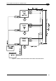
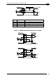

25-PIN CABLE ELECTRICAL CONNECTIONS
5
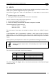
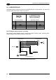
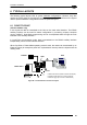
The output
signals are fully programmable being determined by the configured
Activation/Deactivation events, Deactivation Timeout or a combination of the two. Refer to
the Digital I/O folder in the VisiSet™ Help On Line for further details.
USER INTERFACE
O+
8/11
22/12
O-
Matrix 200™
Vext 30 Vdc max.
C
E
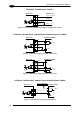
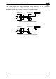
Figure 82 - Open Emitter Output Connection
USER INTERFACE
O+
8/11
22/12
O-
Matrix 200™
Vext 30 Vdc max.
C
E
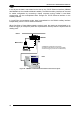
Figure 83 - Open Collector Output Connection
67