
Instruction manual

25-PIN CABLE ELECTRICAL CONNECTIONS
5
5.3.1 RS232 Interface
The RS232 interface can be used for Point-to-Point, Pass Through or Master/Slave
connections. When it is connected to the host computer it allows both transmission of code
data and reader configuration by VisiSet™.
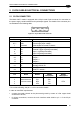
The following pins of the 25-pin connector are used for RS232 interface connection:
Pin Name Function
2 TX Transmit Data
3 RX Receive Data
4 RTS Request To Send
5 CTS Clear To Send
7 GND Ground
It is always advisable to use shielded cables. The overall maximum cable length must be
less than 15 m (49.2 ft).
Matrix 200™
7
4
5
3
GND
RTS
CTS
RX
TX
2
USER INTERFACE
GND
CTS
RTS
TXD
RXD
1
Chassis
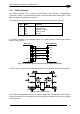
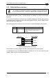
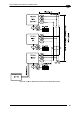
Figure 62 - RS232 Main Interface Connections Using Hardware Handshaking
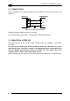
The RTS and CTS signals control data transmission and synchronize the connected devices.
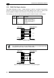
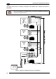
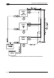
Figure 63 - RS232 Control Signals
If the RTS/CTS handshaking protocol is enabled, Matrix 200™ activates the RTS output to
indicate a message is to be transmitted. The receiving unit activates the CTS input to enable
the transmission.
53