
Instruction manual

MATRIX 200™ REFERENCE MANUAL
5
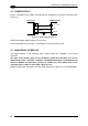
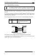
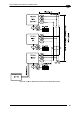
5.2 POWER SUPPLY
Power is supplied to the reader through the pins provided on the 25-pin connector (see
Figure 61):
Earth Ground
CHASSIS
VGND
V+ (10 - 30 Vdc)
13
25
1
Vdc
GND
CHASSIS
POWER SUPPLY
Matrix 200™
Figure 61 - Power Supply Connection
The allowed supply voltage range is 10 to 30 Vdc.
It is recommended to connect pin 1 (CHASSIS) to a common earth ground.
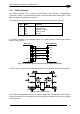
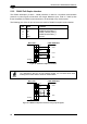
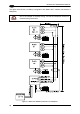
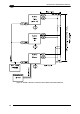
5.3 MAIN SERIAL INTERFACE
The signals relative to the following serial interface types are available on the 25-pin
connector:
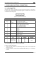
The main serial interface type and its parameters (baud rate, data bits, etc.) can be
defined by the user via VisiSet™ software. The RS485 half duplex is automatically set
whenever MUX32 communication protocol is enabled. For more details refer to the
"Communication" folder in the VisiSet™ Help On Line.
Details regarding the connections and use of the interfaces are given in the next paragraphs.
52