
Instruction manual

INSTALLATION
3
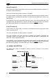
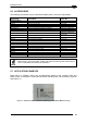
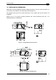
3.2 MECHANICAL DIMENSIONS
Matrix 200™ can be installed to operate in different positions. The four screw holes (M3 x 4)
on the body of the reader are for mechanical fixture (Figure 27).
The diagra
m below gives the overall dimensions of the reader and may be used for its
installation.
Refer to par. 3.3 for various mounting solutions and correct positioning and chp. 7 for
Reading Distance considerations.
50
[1.97]
25
[0.98]
7
[0.28]
[1.77]
45
15
[0.59]
13
[0.51]
11
[0.43]
[0.98]
25
10
[0.39]
Figure 27 – Straight Model Overall Dimensions
54
[2.13]
25
[0.98]
9
[0.35][0.28]
7
[1.77]
45
15
[0.59]
[0.51]
13
32
[1.26]
25
[0.98]
[0.43]
11
mm
[in]
mm
[in]
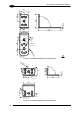
Figure 28 – 90° Model Overall Dimensions
29