MATRIX-2000™ Reference Manual
Datalogic Automation S.r.l. Via S. Vitalino 13 40012 - Lippo di Calderara di Reno Bologna - Italy Matrix-2000™ Reference Manual Ed.: 06/2008 ALL RIGHTS RESERVED Datalogic reserves the right to make modifications and improvements without prior notification. Datalogic shall not be liable for technical or editorial errors or omissions contained herein, nor for incidental or consequential damages resulting from the use of this material.
CONTENTS REFERENCES ............................................................................................................. v Conventions.................................................................................................................. v Reference Documentation ............................................................................................ v Service and Support ..................................................................................................... v Patents..
5.1 5.2 5.3 5.4 5.5 5.5.1 5.5.2 5.5.3 5.6 5.7 5.8 5.9 5.10 DB25-Pin Connector................................................................................................... 43 DB9-Pin Connector (RS232 Auxiliary Port) ................................................................ 44 RJ45 8-Pin Connector (Ethernet) ............................................................................... 44 Power Supply...............................................................................................
REFERENCES CONVENTIONS This manual uses the following conventions: "User" refers to anyone using a Matrix-2000™ reader. "Reader" refers to the Matrix-2000™ reader. "You" refers to the System Administrator or Technical Support person using this manual to install, configure, operate, maintain or troubleshoot a Matrix-2000™ reader.
COMPLIANCE For installation, use and maintenance it is not necessary to open the reader.
HANDLING The Matrix-2000™ is designed to be used in an industrial environment and is built to withstand vibration and shock when correctly installed, however it is also a precision product and therefore before and during installation it must be handled correctly to avoid damage. • avoid that the readers are dropped (exceeding shock limits). • do not fine tune the positioning by striking the reader or bracket.
viii • do not weld the reader into position which can cause electrostatic, heat or reading window damage. • do not spray paint near the reader which can cause reading window damage.
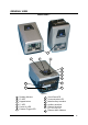
GENERAL VIEW Matrix-2000™ 1 2 3 4 5 6 7 8 12 9 11 10 Figure A 1 2 3 4 5 6 Reading Window F2 LED Keypad button F1 LED Power On LED External Trigger LED 7 8 9 10 11 Good Read LED Communication LED Main/Auxiliary Interface Auxiliary Interface Ethernet Interface (for 21XX models only) 12 Ethernet MAC Address ix
x
RAPID CONFIGURATION 1 1 RAPID CONFIGURATION STEP 1 – CONNECTING THE SYSTEM To connect the system in a Stand Alone configuration, you need the hardware indicated in Figure 1. In this layout the data is transmitted to the Host on the main serial interface. The RS232 auxiliary interface can be used for reader configuration by connecting a laptop computer running VisiSet™.
Matrix-2000™ Reference Manual 1 CBX100/CBX500 Pinout for Matrix-2000™ The table below gives the pinout of the CBX100/CBX500 terminal block connectors.
RAPID CONFIGURATION 1 DB25-Pin Connector The Matrix-2000™ reader is equipped with a 25-pin male D-Sub connector for connection to the power supply and input/output signals.
Matrix-2000™ Reference Manual 1 DB9-Pin Connector (RS232 Auxiliary Port) There is also a separate 9-pin female D-sub connector for the Auxiliary port connection with the following pinout: 1 5 9 6 Figure 3 - 9-pin female D-Sub Connector 9-pin female D-sub connector pinout Pin 2 3 5 1,4,6,7,8,9 CAUTION Name TX RX GND N.C.
RAPID CONFIGURATION 1 STEP 2 – MOUNTING AND POSITIONING THE SYSTEM 1. To mount the Matrix-2000™, use the mounting bracket to obtain the most suitable position for the reader as shown in the figures below. Figure 5 - Positioning with Mounting Bracket 2. When mounting the Matrix-2000™ take into consideration these three ideal label position angles: Pitch or Skew 10° to 20° and Tilt 0°, although the reader can read a code at any Tilt angle.
Matrix-2000™ Reference Manual 1 STEP 3 – AUTOLEARNING CONFIGURATION An autolearning procedure is available to reduce installation time.
RAPID CONFIGURATION NOTE 1 Autolearning configuration parameters can be saved to temporary memory only by selecting the "Autolearning Setup>Store Memory" parameter in VisiSet™. The Autolearning function on the keypad button can also be disabled by the user via VisiSet™. Auto Learn (F2) green Figure 7 – Auto Learn Function Repeat the procedure if needed, to program different code symbologies, however you must present only one code at a time to the reader.
Matrix-2000™ Reference Manual 1 To cancel the Positioning function, press and hold the keypad button at any time during the procedure: the F1 LED will stop blinking and Matrix-2000™ will emit a long low pitched beep. Positioning (F1) yellow Figure 8 – Positioning Function Restore Default (Optional) At any time you can use the Restore Default procedure to return the reader to the factory default settings. 1.
RAPID CONFIGURATION 1 STEP 4 – INSTALLING VISISET™ CONFIGURATION PROGRAM VisiSet™ is a Datalogic reader configuration tool providing several important advantages: • Autolearning Wizard for rapid configuration and for new users; • Defined configuration directly stored in the reader; • Communication protocol independent from the physical interface allowing to consider the reader as a remote object to be configured and monitored.
Matrix-2000™ Reference Manual 1 STEP 5 – CONFIGURATION USING AUTOLEARNING WIZARD 1. Select the Autolearning Wizard button from the Main menu. 2. Place the desired code in front of the reader at the correct reading distance (depending on the model, see the Reading Features table in par. 7.1). 3. Press the "Positioning" button. The reader continuously acquires images and gives visual feedback in the view image window to indicate when the code is centered with respect to the reader's FOV.
RAPID CONFIGURATION 1 The reader flashes once acquiring the image and auto determines the best exposure and gain settings. If the code symbology is enabled by default, the code will also be decoded. 5. If the code symbology is not enabled by default, select a Code Setting Mode choice and press the "Code Setting" button. The Autolearning Result section of the Autolearning Wizard window shows the parameter settings and the code type results. 6. Select a Saving Options choice and press the "Save" button.
Matrix-2000™ Reference Manual 1 ADVANCED READER CONFIGURATION For further details on advanced product configuration, refer to the VisiSet™ Help On-Line. The following are alternative or advanced reader configuration methods: Advanced Configuration Using VisiSet™ Advanced configuration can be performed through the VisiSet™ program by selecting Device> Get Configuration From Temporary Memory to open the Parameter Setup window in off-line mode.
GENERAL FEATURES 2 2 GENERAL FEATURES 2.1 INTRODUCTION Matrix-2000™ is a Datalogic compact 2D reader designed and produced to be a high performance affordable solution for both linear and two-dimensional code reading applications. Matrix-2000™ has been developed for use in numerous applications, including PCB and electronic manufacturing, packaging lines, small item tracking, analysis machines and document handling systems, and can also be easily integrated into a wide range of OEM solutions.
2 Matrix-2000™ Reference Manual 2.
GENERAL FEATURES 2 The following indicators are located on the top of the reader: PWR red LED indicates that the reader is connected to the power supply (see Figure A, 5). TRIG yellow LED indicates external trigger activity (Figure A, 6). READ red LED signals successful code decoding (Figure A, 7). It is also used to signal successful startup. At power on this LED turns on and after a few seconds turns off. If the startup is not successful, this LED remains on.
Matrix-2000™ Reference Manual 2 2.3 MODEL DESCRIPTION The Matrix-2000™ reader is available in different versions according to the following characteristics: MATRIX - 2XXX-X Device Connectivity Optics Image Sensor Other Options 0 = RS232/RS485 + RS232 1 = RS232/RS485 + RS232+ Ethernet 1 = Ultra High Density (UHD) 2 = High Density (HD) 3 = Standard Density (STD) 4 = Low Density (LD) 5 = Medium Range (MR) 6 = Long Range (LR) 1 = VGA CCD R = 90° Reading Window 2.4 ACCESSORIES Order No.
GENERAL FEATURES 2 2.5 APPLICATION EXAMPLES Matrix-2000™ is profitably used in the omnidirectional reading of 2D, stacked, linear and postal codes. The powerful LED illuminator, the Matrix 2XX1 60 fps CCD sensor and the 400 MHz CPU allow the decoding of fast moving codes (over 6.0 m/s) on industrial printing lines (see Figure 13) and in automated document handling and mail processing systems (see Figure 14).
2 Matrix-2000™ Reference Manual Matrix-2000™ assures the reading of deformed and / or overprinted codes, even though damaged or printed on high reflective surfaces (see Figures 15,16,17).
GENERAL FEATURES 2 Figure 19 - Dot Peening Marking on Metal Surface with Multi-dot per Code Element Figure 20 - Directly Marked Dot Matrix Code Characterized by Outstanding Separation Distance between Adjacent Code Elements Figure 21 - Data Matrix Code Directly Marked on PCB Surface by Using Laser Etching Technology Figure 22 - Dot Matrix Code Directly Marked on PCB Copper Pad by Using Ink-Jet Technology 19
Matrix-2000™ Reference Manual 2 2.6 EXTERNAL LIGHTING SYSTEMS In some direct part marking applications best reading results are obtained by using an external lighting system. A series of accessory illuminators are available which cover a variety of applications.
GENERAL FEATURES 2 The LT-210 Mini Spot Lighting System provides a high intensity light source designed for the following applications: • with uneven, noisy and scratched surfaces • where dot peening or laser etching codes are directly marked onto metal surfaces or PCBs and need to be highlighted. Here the use of more than one Spot Light can remove any shadowing effect. • in the presence of highly reflective surfaces (metal, glass, etc.) causing direct reflections.
2 Matrix-2000™ Reference Manual The LT-316 60° Dark Field Ring Lighting System is designed for reading codes produced by Dot Peening (especially by a 120° stylus) or Laser Etching on flat, reflective parts. Figure 28 - LT-316 60° Dark Field Ring Lighting System The LT-410 Coaxial Lighting System is an axial diffuse illuminator designed for reading codes produced by Dot Peening or Laser Etching on flat parts having a matte, specular or mixed surface reflectivity.
GENERAL FEATURES 2 The LT-511 Dome Lighting System is a diffuse dome light designed for reading printed label or Direct Marking codes on parts with a curved surface. Figure 31 - LT-511 Dome Lighting System The LT-630 Four Bar Lighting System is designed for Code verification applications according to ISO/IEC 15415 or ISO/IEC 15416 specifications.
MATRIX-2000™ REFERENCE MANUAL 3 3 INSTALLATION 3.1 PACKAGE CONTENTS Verify that the Matrix-2000™ reader and all the parts supplied with the equipment are present and intact when opening the packaging; the list of parts includes: Matrix-2000™ reader Quick Reference Guide Test Chart Matrix family CD-ROM Auxiliary port connector cover Mounting kit • Mounting screws and washers (4 ea.
INSTALLATION 3 3.2 MECHANICAL DIMENSIONS Matrix-2000™ can be installed to operate in different positions. The eight screw holes (M4 x 5) on the body of the reader are for mechanical fixture (Figure 34). The diagram below gives the overall dimensions of the reader and may be used for its installation. Refer to paragraphs 3.3 and 7.1 for correct positioning. 57 [2.24] = 73 [2.87] 57 [2.24] 18.1 [0.71] M4 x 5 n°4 57 [2.24] 4 [0.16] mm [inch] M4 x 5 n°4 121 [4.76] 57 [2.24] 28.1 [1.
MATRIX-2000™ REFERENCE MANUAL 3 .2 Ø 4 17] . [Ø0 95 [3.74] 121 [4.76] 73 [2.87] 37 [1.46] 73 [2.87] 15 [0.59] mm [inch] 47.5 [1.87] 2 [0.08] Figure 35 - Overall dimensions - 90° model 3.2.1 47.5 [1.87] 57 [2.24] 95 [3.74] 2 8. ] Ø .3 2 0 [Ø 4.2 [0.
INSTALLATION 3 3.3 POSITIONING Matrix-2000™ is able to decode code labels at a variety of angles, however significant angular distortion may degrade reading performance. When mounting Matrix-2000™, take into consideration these ideal label position angles: Pitch or Skew 10° to 20° and Tilt 0°. Note: Since Matrix-2000™ is omni-directional on the code plane, the Pitch and Skew angles have the same significance with respect to the code plane.
MATRIX-2000™ REFERENCE MANUAL 3 The Tilt angle is represented by the value T in Figure 40. Matrix-2000™ can read labels with any tilt angle. Figure 40 - Tilt angle Position the reader so that the distance from the reading window to the code surface is that indicated in par. 7.1 for your model.
CBX ELECTRICAL CONNECTIONS 4 4 CBX ELECTRICAL CONNECTIONS All Matrix-2000™ models can be connected to a CBX connection box through one of the available CAB-Sxx accessory cables. These accessory cables terminate in a 25-pin female D-sub connector on the Matrix-2000™ side and in a 25-pin male D-sub connector on the CBX side.
MATRIX-2000™ REFERENCE MANUAL 4 NOTE To avoid electromagnetic interference when the reader is connected to a CBX connection box, verify the jumper positions in the CBX as indicated in its Installation Manual. 4.1 POWER SUPPLY Power can be supplied to the reader through the CBX100/500 spring clamp terminal pins as shown in Figure 41: Power Supply VGND V+ in Earth Ground Figure 41 - Power Supply Connections The power must be between 10 and 30 Vdc only.
CBX ELECTRICAL CONNECTIONS 4.2.1 4 RS232 Interface The RS232 interface can be used for Point-to-Point, Pass Through or Master/Slave connections. When it is connected to the host computer it allows both transmission of code data and reader configuration by VisiSet™. The following pins are used for RS232 interface connection: CBX100/500 TX RX RTS CTS SGND Function Transmit Data Receive Data Request To Send Clear To Send Signal Ground It is always advisable to use shielded cables.
MATRIX-2000™ REFERENCE MANUAL 4 4.2.2 RS485 Full-Duplex Interface The RS485 full-duplex (5 wires + shield) interface is used for non-polled communication protocols in point-to-point connections over longer distances (max 1200 m / 3940 ft) than those acceptable for RS232 communications or in electrically noisy environments.
CBX ELECTRICAL CONNECTIONS 4.2.3 4 RS485 Half-Duplex Interface The RS485 half-duplex (3 wires + shield) interface is used for polled communication protocols. It can be used for Multidrop connections with a Datalogic Multiplexer, (see par. 6.4) exploiting a proprietary protocol based on polled mode called MUX32 protocol, where a master device polls slave devices to collect data.
4 MATRIX-2000™ REFERENCE MANUAL Figure 47 – Matrix-2000™ Multidrop Connection to a Multiplexer 34
CBX ELECTRICAL CONNECTIONS 4 4.3 AUXILIARY RS232 INTERFACE The RS232 auxiliary interface is available for Point-to-Point, Pass Through or Master/Slave connections. When it is connected to the host computer it allows both transmission of code data and reader configuration by VisiSet™. The parameters relative to the aux interface (baud rate, data bits, etc.) as well as particular communication modes such as LOCAL ECHO can be defined through the Communication folder of the VisiSet™ utility program.
MATRIX-2000™ REFERENCE MANUAL 4 4.4 INPUTS There are two optocoupled polarity insensitive inputs available on the reader: Input 1 (External Trigger) and Input 2, a generic input: The External Trigger can be used in One Shot Mode or in Phase Mode.
CBX ELECTRICAL CONNECTIONS 4 EXTERNAL TRIGGER INPUT CONNECTIONS USING MATRIX-2000™ POWER CAUTION Power is available directly to the Input Device, independently from the Power Supply Switch inside the CBX.
MATRIX-2000™ REFERENCE MANUAL 4 CBX100/500 +V I2A I2B -V Function Power Source - Inputs Input 2 A (polarity insensitive) Input 2 B (polarity insensitive) Power Reference - Inputs INPUT 2 CONNECTIONS USING MATRIX-2000™ POWER CAUTION Power is available directly to the Input Device, independently from the Power Supply Switch inside the CBX.
CBX ELECTRICAL CONNECTIONS 4 Input Device Pulled up to External Input Device Power Input Signal Figure 55 - NPN Input 2 Using External Power 4.5 OUTPUTS Thee optocoupled general purpose outputs are available. The meaning of the three outputs can be defined by the user. They are typically used either to signal the data collection result or to control an external lighting system.
MATRIX-2000™ REFERENCE MANUAL 4 OUTPUT CONNECTIONS USING MATRIX-2000™ POWER CAUTION Power is available directly to the Output Device, independently from the Power Supply Switch inside the CBX.
CBX ELECTRICAL CONNECTIONS 4 4.6 EXTERNAL LIGHTING SYSTEMS If an External Illuminator is used, it can be powered from the CBX connection box. It must be connected to the Vdc and GND terminal clamps. CAUTION Power is available directly to the Illuminator, independently from the Power Supply Switch inside the CBX. In the case of the LT-100, LT-200 or LT-300 illuminators, one of the available digital outputs must be connected as the control signal.
MATRIX-2000™ REFERENCE MANUAL 4 4.7 USER INTERFACE - HOST The following table contains the pinout for standard RS232 PC Host interface. For other user interface types please refer to their own manual.
19-PIN CONNECTOR ELECTRICAL CONNECTIONS 5 5 MATRIX-2000™ CONNECTOR ELECTRICAL CONNECTIONS 5.1 DB25-PIN CONNECTOR The Matrix-2000™ reader is equipped with a 25-pin male D-Sub connector for connection to the power supply and input/output signals.
MATRIX-2000™ REFERENCE MANUAL 5 5.2 DB9-PIN CONNECTOR (RS232 AUXILIARY PORT) There is also a separate 9-pin female D-sub connector for the Auxiliary port connection with the following pinout: 1 5 9 6 Figure 62 - 9-pin female D-Sub Connector 9-pin female D-sub connector pinout Pin 2 3 5 1,4,6,7,8,9 CAUTION Name TX RX GND N.C.
19-PIN CONNECTOR ELECTRICAL CONNECTIONS 5 5.4 POWER SUPPLY Power is supplied to the reader through the pins provided on the 25-pin connector (see Figure 64): USER INTERFACE MATRIX Vdc GND Chassis 9/13 V+ (10 - 30 Vdc) 23/25 V- (Ground) 1 SHIELD CHASSIS Earth Ground Earth Ground Figure 64 - Power Supply Connection The allowed supply voltage range is 10 to 30 Vdc. 5.5 MAIN SERIAL INTERFACE The signals relative to the following serial interface types are available on the 25-pin connector.
MATRIX-2000™ REFERENCE MANUAL 5 MATRIX TX RX RTS CTS GND_ISO Chassis SHIELD USER INTERFACE 2 3 RXD TXD 4 5 7 Handshaking Signals Reference Ground 1 Earth Ground Earth Ground Figure 65 - RS232 Main Interface Connections The RTS and CTS signals control data transmission and synchronize the connected devices. Figure 66 - RS232 Control Signals If the RTS/CTS handshaking protocol is enabled, Matrix-2000™ activates the RTS output to indicate a message is to be transmitted.
19-PIN CONNECTOR ELECTRICAL CONNECTIONS 5.5.2 5 RS485 Full-Duplex Interface The RS485 full-duplex (5 wires + shield) interface is used for non-polled communication protocols in point-to-point connections over longer distances (max 1200 m / 3940 ft) than those acceptable for RS232 communications or in electrically noisy environments.
MATRIX-2000™ REFERENCE MANUAL 5 5.5.3 RS485 Half-Duplex Interface The opto-isolated RS485 half-duplex (3 wires + shield) interface is available for polled communication protocols. It can be used for multidrop connections with a Datalogic Multiplexer, (see Figure 70 and par. 6.4) exploiting a proprietary protocol based on polled mode called MUX32 protocol, where a master device polls slave devices to collect data.
19-PIN CONNECTOR ELECTRICAL CONNECTIONS 5 The figure below shows a multidrop configuration with Matrix-2000™ readers connected to a Multiplexer. This is an example of multidrop wiring. Consult the multiplexer manual for complete wiring instructions.
MATRIX-2000™ REFERENCE MANUAL 5 5.6 AUXILIARY RS232 INTERFACE The RS232 auxiliary interface is available for Point-to-Point, Pass Through or Master/Slave connections. When it is connected to the host computer it allows both transmission of code data and reader configuration by VisiSet™. The parameters relative to the aux interface (baud rate, data bits, etc.) as well as particular communication modes such as LOCAL ECHO can be defined through the Communication folder of the VisiSet™ utility program.
19-PIN CONNECTOR ELECTRICAL CONNECTIONS 5 5.7 ETHERNET INTERFACE (MATRIX-21XX MODELS ONLY) The Ethernet Interface can be used for TCP/IP communication with a remote or local host computer by connecting the reader to either a LAN or directly to a host PC.
MATRIX-2000™ REFERENCE MANUAL 5 On the Matrix-2000™ Ethernet interface the following communication channels are available: • Data Socket • Image Socket • Image FTP Client • HTTP Server • Email Client • Ethernet IP For further details refer to the Ethernet Folder in the VisiSet™ Help On Line and to the "Matrix Ethernet Service Guide.pdf" document provided as supplementary documentation. 5.
19-PIN CONNECTOR ELECTRICAL CONNECTIONS 5 The connections are indicated in the following diagrams: Pin 9 18 19 25 Name Vdc I1A I1B GND Function Power Supply input voltage + External Trigger A (polarity insensitive) External Trigger B (polarity insensitive) Power Supply input voltage - When current flows through the I1A-B input (External Trigger), the yellow TRIG LED (Figure A, 6) is on.
MATRIX-2000™ REFERENCE MANUAL 5 EXTERNAL TRIGGER INPUT CONNECTIONS USING EXTERNAL POWER Vext 30 Vdc max. EXTERNAL TRIGGER Matrix-2000™ V VCC + ~ ~ 18 I1A 19 I1B - Signal I in Figure 78 - External Trigger PNP Using External Power Vext 30 Vdc max.
19-PIN CONNECTOR ELECTRICAL CONNECTIONS 5 INPUT 2 CONNECTIONS USING EXTERNAL POWER Vext 30 Vdc max. INPUT DEVICE Matrix-2000™ V VCC + ~ ~ - 6 I2A 10 I2B Signal I in Figure 82 - Input PNP Using External Power Vext 30 Vdc max. INPUT DEVICE Matrix-2000™ VCC + ~ ~ - 6 I2A 10 I2B V Signal Figure 83 - Input NPN Using External Power 5.9 OUTPUTS Three opto-coupled general purpose outputs are available on the 25-pin connector. The meaning of the three outputs can be defined by the user.
MATRIX-2000™ REFERENCE MANUAL 5 The output signals are fully programmable being determined by the configured Activation/Deactivation events, Deactivation Timeout or a combination of the two. Refer to the Digital I/O folder in the VisiSet™ Help On Line for further details.
19-PIN CONNECTOR ELECTRICAL CONNECTIONS 5 5.10 USER INTERFACE RS232 PC-side connections 1 5 1 6 14 9 9-pin male connector Pin 2 3 5 7 8 13 Name RX TX GND RTS CTS 25 25-pin male connector Pin 3 2 7 4 5 Name RX TX GND RTS CTS How To Build A Simple Interface Test Cable: The following wiring diagram shows a simple test cable including power, external (pushbutton) trigger and PC RS232 COM port connections.
MATRIX-2000™ REFERENCE MANUAL 6 6 TYPICAL LAYOUTS The following typical layouts refer to system hardware configurations. However, they also require the correct setup of the software configuration parameters. Dotted lines in the figures refer to optional hardware configurations within the particular layout. 6.1 POINT-TO-POINT In this layout the data is transmitted to the Host on the main serial interface.
TYPICAL LAYOUTS 6 6.2 PASS-THROUGH Pass-through mode allows two or more devices to be connected to a single external serial interface. Each reader transmits the messages received by the Auxiliary interface onto the Main interface. All messages will be passed through this chain to the host. When One Shot or Phase Mode operating mode is used, the reader can be activated by an External Trigger (for example a pulse from a photoelectric sensor) when the object enters its reading zone.
MATRIX-2000™ REFERENCE MANUAL 6 6.3 RS232 MASTER/SLAVE The RS232 master/slave connection is used to collect data from several readers to build either a multi-point or a multi-sided reading system; there can be one master and up to 9 slaves connected together. The Slave readers use RS232 only on the main and auxiliary serial interfaces. Each slave reader transmits the messages received by the auxiliary interface onto the main interface. All messages will be passed through this chain to the Master.
TYPICAL LAYOUTS 6 6.4 MULTIPLEXER Each reader is connected to a Multiplexer (for example MX4000) with the RS485 half-duplex main interface through a CBX connection box. Before proceeding with the connection it is necessary to select the MUX32 communication protocol and the multidrop address for each reader.
MATRIX-2000™ REFERENCE MANUAL 6 6.5 ETHERNET CONNECTION (MATRIX-21XX MODELS ONLY) For Matrix-21XX models, the Ethernet connection is possible in two different layouts. In both layouts, before proceeding with the connection, it is necessary to configure the reader Ethernet parameters via VisiSet™. For further details, see the Ethernet Folder in the VisiSet™ Help On Line. In a Point-to-Point layout the reader is connected to a local host by using a cable with a crossover adapter.
TYPICAL LAYOUTS 6 When using a Local Area Network (LAN), one or more Matrix-21XXs can be connected to the network by using straight through cables: CAB-Sxx Matrix-2000™ 3 CBX 2 Power 1 Host NETWORK Ethernet Interface (Straight Through Cables) Auxiliary Serial Interface (Local Echo) (RS232) External Trigger (for One Shot or Phase Mode) Figure 92 - Ethernet Network Layout 63
MATRIX-2000™ REFERENCE MANUAL 7 7 READING FEATURES 7.1 READING DISTANCE AND FOV The following figures represent the Reading Distance and Field of View (FOV) based on the Matrix-2000™ model. Position the reader so that the distance from the reading window to the code surface is that indicated in the figure below for your model. 2X11 UHD focus distance 60 mm (2.36 in) 2X21 HD FOV 17 x 13 mm (0.67 x 0.51 in) code surface focus distance 85 mm (3.35 in) FOV 25 x 19 mm (0.98 x 0.
READING FEATURES 7 Special models with different FOV and focus distance are available on request. Refer to your local Datalogic distributor. All distances indicated from the reading window to the code surface are the same for 90° models. READING FEATURES Up to 60 frames/sec. with VGA images Frame Rate Readable Codes per Frame Pitch Up to 100 10° - 35° Tilt 0° - 360° MODELS Focus Distance mm (in) Field of View (1) mm (in) ppi(2) Typ. Linear and Stacked Code Resolution mm (mils) Typ.
MATRIX-2000™ REFERENCE MANUAL 7 7.2 MAXIMUM LINE SPEED CALCULATION The Exposure Time (or Shutter) parameter defines the time during which the image will be exposed to the reader sensor to be acquired. This parameter depends heavily on the environmental conditions (external lighting system, image contrast etc.). In general, a longer time corresponds to a lighter image but is susceptible to blurring due to the code movement; a shorter exposure time corresponds to a darker image.
READING FEATURES 7 The Internal Lighting Mode parameter allows to set the operating mode of the internal lighting system. The possible values are: • Disabled: the built-in LED array is turned off all the time. This option can be useful if using an external lighting system; • Always ON: the built-in LED array is turned on all the time at the lowest power level. This option is useful if the LED-array blinking (Strobed operating mode) disturbs the operator.
MATRIX-2000™ REFERENCE MANUAL 8 8 SOFTWARE CONFIGURATION Software configuration of your Matrix-2000™ for static reading or simple code reading applications can be accomplished by the Rapid Configuration procedure using the onboard keypad Autolearning Configuration (which requires no external configuration program) or by using the VisiSet™ Autolearning Wizard for easy setup. These procedures are described in chapter 1.
SOFTWARE CONFIGURATION 8 8.3 STARTUP After completing the mechanical and electrical connections to Matrix-2000™, you can begin software configuration as follows: 1. Power on the Matrix-2000™ reader. Wait for the reader startup. The system bootstrap requires a few seconds to be completed. The reader automatically enters Run Mode. 2. Run the VisiSet™ program. 3. Press Connect on the VisiSet™ menu bar. The PC will automatically connect to the Matrix-2000™ reader.
MATRIX-2000™ REFERENCE MANUAL 8 8.3.
SOFTWARE CONFIGURATION 8 Figure 97 - Options – Communication: Serial Port Figure 98 - Options – Communication: Ethernet 71
MATRIX-2000™ REFERENCE MANUAL 8 8.4 CONFIGURATION Once connected to Matrix-2000™ as described in par. 8.3, you can modify the configuration parameters as follows: 1. Press the Calibration Tool button from the Main Menu. Matrix-2000™ will download its permanent memory configuration parameters with the default values (if it is the first time) to VisiSet™. The Calibration Tool window will be displayed together with the Parameter Setup window working in Interactive Mode (see par. 8.4.1 and par. 8.4.3). 2.
SOFTWARE CONFIGURATION 8.4.1 8 Edit Reader Parameters The Parameter Setup window displays the configuration parameters grouped in a series of folders. Each parameter can be modified by selecting a different item from the prescribed list in the box, or by typing new values directly into the parameter box. By right clicking the mouse when positioned over the name of a specific Parameter or Group, a pop-up menu appears allowing you to directly manage that particular parameter or group.
MATRIX-2000™ REFERENCE MANUAL 8 Parameters to verify/modify: Operating Mode Sets the parameters which customize the reader operating mode starting from three main modes: One Shot: acquires a single image based on the selected value for the Acquisition Trigger and Acquisition Trigger Delay. Continuous: continuously acquires images with a rate up to the maximum allowable frame rate per second for the given sensor depending on the decoding time and the Region of Interest settings.
SOFTWARE CONFIGURATION 8 When all the configuration parameters are set correctly, save them to the Matrix-2000™ reader by pressing the Send button. See Figure 99. For successive configuration of other readers or for backup/archive copies, it is possible to save the configuration onto your PC by selecting the Save Configuration File option from the File menu. From the File menu, you can also Save Configuration As Text File for a human readable version.
MATRIX-2000™ REFERENCE MANUAL 8 Environmental Parameters regard the device Identity and Position in a Network (Master/Slave RS232, MUX32, Ethernet) and are not influenced by the "Send Default Configuration" and "Send Configuration" commands. This allows individual devices to be configured differently without affecting their recognized position in the network.
SOFTWARE CONFIGURATION 8 For device replacement it is necessary to send the previously saved configuration (both Configuration and Environmental parameters) to the new device.
MATRIX-2000™ REFERENCE MANUAL 8 8.4.3 Calibration VisiSet™ provides a Calibration Tool to maximize the reading performance by tuning the acquisition parameters and the time of the delayed triggers. By selecting the Calibration Tool from the VisiSet™ Main Menu (F), the following window appears together with the Parameter Setup window: Figure 100 - Calibration OK This tool provides a "real-time" image display while Matrix-2000™ is reading.
SOFTWARE CONFIGURATION 8 The following examples show some of the typical conditions occurring during the installation: Under-exposure: To correct this result it is recommended to change the following parameters in their order of appearance: 1. increase the Exposure Time (x 10 µs) 2. increase the Gain In general, a longer exposure time corresponds to a lighter image but is susceptible to blurring due to code movement. Exposure time is also limited by the Internal Lighting mode parameter.
MATRIX-2000™ REFERENCE MANUAL 8 Over-exposure: To correct this result it is recommended to change the following parameters in their order of appearance: 1. decrease the Gain 2.
SOFTWARE CONFIGURATION 8 Moving code out of the Field of View: To correct this result and have the code completely visible in F.O.V.
MATRIX-2000™ REFERENCE MANUAL 8 8.4.4 Multi Image Acquisition Settings When controlled variable conditions occur in the application, Multiple Image Acquisition Settings (up to 10), can be defined to create a database of parameter groups that handle each specific application condition. This database of pre-defined settings functions cyclically and therefore automatically improves system flexibility and readiness.
SOFTWARE CONFIGURATION 8.4.6 8 Region Of Interest Windowing In order to satisfy very high throughput applications, higher frame rates can be achieved using the powerful Region Of Interest Windowing parameters in the Calibration parameter setup menu. Region Of Interest Windowing allows defining a region or window within the reader FOV. The Top, Bottom, Left and Right parameters allow to precisely define the image window to be processed, visualized and saved.
MATRIX-2000™ REFERENCE MANUAL 8 8.4.7 Direct Part Marking Applications Decoding Method: Direct Marking For Data Matrix and QR code the Decoding Method parameter selects the decoding algorithm according to the printing/marking technique used to create the symbol and on the overall printing/marking quality. The Direct Marking selection improves the decode rate for low quality Direct Part Mark codes and in general for Direct Part Mark codes with dot peening type module shapes.
SOFTWARE CONFIGURATION 8 Image Filter Sets the filter to be applied to the image before being processed. This parameter can be used to successfully decode particular ink-spread printed codes (ex. direct part mark codes). A different filter can be applied to each Image Acquisition Setting. The Erode Filter enlarges the image dark zones to increase readability. Before - No Read After - Readable Erode The Dilate Filter enlarges the image white zones to increase readability.
MATRIX-2000™ REFERENCE MANUAL 8 8.5 IMAGE CAPTURE AND DECODING By using the Capture Image and Decode Last Image functions from the VisiSet™ Main menu, you can get information about the image decodable codes in terms of Symbology, encoded Data, Position and Orientation, Decode Time and Code Quality Assessment Metrics. Figure 104 - Capture and Decoding Functions 8.
MAINTENANCE 9 9 MAINTENANCE 9.1 CLEANING Clean the reading window (see Figure A, 1) periodically for continued correct operation of the reader. Dust, dirt, etc. on the window may alter the reading performance. Repeat the operation frequently in particularly dirty environments. Use soft material and alcohol to clean the window and avoid any abrasive substances.
MATRIX-2000™ REFERENCE MANUAL 10 10 TROUBLESHOOTING 10.1 GENERAL GUIDELINES • When wiring the device, pay careful attention to the signal name (acronym) on the CBX100/500 spring clamp connectors (chp. 4). If you are connecting directly to the Matrix2000™ DB25-pin connector pay attention to the pin number of the signals (chp. 5). • If you need information about a certain reader parameter you can refer to the VisiSet™ program help files.
TROUBLESHOOTING 10 TROUBLESHOOTING GUIDE Problem Suggestion One Shot or Phase Mode using serial trigger source: the ”TRIGGER” LED is not blinking. • In the Operating Mode folder check the settings for • • • Phase Mode: the ”TRIGGER" LED is correctly blinking but no image is displayed in VisiSet™ Calibration Tool window. Continuous Mode: the ”TRIGGER” LED is not blinking.
MATRIX-2000™ REFERENCE MANUAL 10 TROUBLESHOOTING GUIDE Problem Suggestion are incorrect, corrupted or incomplete. • In VisiSet™ Communication folder check the settings of Header and Terminator String parameters. • In VisiSet™ Data Collection folder, check the settings of How do I obtain my reader Serial Number? • • • How do I obtain my reader Order Number? 90 • • DATA FORMAT parameter group.
TECHNICAL FEATURES 11 11 TECHNICAL FEATURES ELECTRICAL FEATURES Power Supply Voltage Power Consumption Communication Interfaces Main - RS232 - RS485 full-duplex - RS485 half-duplex Auxiliary - RS232 Ethernet (21xx models only) Inputs Max. Voltage Max. Input Current Outputs VOut (ILoad = 0 mA) Max. VOut (ILoad = 10 mA) Max. PD = VOut × ILoad Max. 10 to 30 Vdc 0.8 to 0.27 A, 8 W max.; 0.5 to 0.
MATRIX-2000™ REFERENCE MANUAL 11 CODE QUALITY VERIFICATION Standard ISO/IEC 16022 ISO/IEC 18004 ISO/IEC 15415 ISO/IEC 15416 AS9132A AIM DPM Supported Symbologies Data Matrix ECC 200 QR Code Data Matrix ECC 200, QR Code Code 128, Code 39, Interleaved 2 of 5, Codabar, Code 93, EAN-8/13, UPC-A/E Data Matrix ECC 200 Data Matrix ECC 200, QR Code USER INTERFACE LED Indicators Keypad Button 92 PWR, TRIG, READ, COM, F1, F2 Configurable via VisiSet™
GLOSSARY AIM (Association for Automatic Identification and Mobility): AIM Global is the international trade association representing automatic identification and mobility technology solution providers. AIM DPM Quality Guideline Standard applicable to the symbol quality assessment of direct part marking (DPM) performed in using two-dimensional bar code symbols. It defines modifications to the measurement and grading of several symbol quality parameters.
Depth of Field The difference between the minimum and the maximum distance of the object in the field of view that appears to be in focus. Diffused Illumination Distributed soft lighting from a wide variety of angles used to eliminate shadows and direct reflection effects from highly reflective surfaces. Direct Part Mark (DPM) A symbol marked on an object using specific techniques like dot peening, laser etching, chemical etching, etc. EEPROM Electrically Erasable Programmable Read-Only Memory.
ISO (International Organization for Standardization): A network of the national standards institutes of several countries producing world-wide industrial and commercial standards. LED (Light Emitting Diode) A low power electronic light source commonly used as an indicator light. It uses less power than an incandescent light bulb but more than a Liquid Crystal Display (LCD).
INDEX Maintenance; 87 Mechanical Dimensions; 25 Model Description; 16 Mounting Matrix-2000™; 26 Multiplexer; 61 A Accessories; 16 Application Examples; 17 Auto Learn; 6 Auxiliary RS232 Interface; 35; 50 O C Outputs; 39; 55 Calibration; 78 CBX Electrical Connections; 29 Compliance; vi P D DB25-Pin Connector; 43 DB9-Pin Connector (RS232 Port); 44 E Edit Reader Parameters; 73 Electrical Connections; 43 Ethernet Connection; 62 Ethernet Interface; 51 External Lighting Systems; 20 G General View; ix Gl
DECLARATION OF CONFORMITY 08 Datalogic Automation S.r.l. Via S.
www.automation.datalogic.