
Installation Manual

STAR-Module 910
InstallationManuaSM910 page 5 of 6
DATALOGIC PROPRIETARY INFORMATIONS
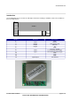
Digital interface
Digital Interface with host system
Data communication with host is implemented using a UART @38400, N, 8, 1 with TDX and RXD negated
values: this means that data lines are low (0 V) in idle state and go high upon a start bit. Host system must
provide to inverter gates between its UART and the STAR-Module 910MHz.
Control is implemented using TX CMD and RX CMD lines and receiving Carrier Detect indication (refer to
operating description for details) .
RF interface
STAR-module has 50Ohm impedance on RF out in TX and RX mode, therefore impedance matching is
required for antenna system of host.
Care must be taken for the proximity of conductive materials or the user’s hand that will cause a mismatch of
the antenna, decreasing the transceiver RF characterics.
Moreover, care must be taken to ensure that the host system doesn’t have spurious emissions in the range
910MHz+/-100kHz, that could cripple receiver sensitivity: it is advised to put a ground plane under the RF
module and to filter the power supply.
Noisy parts, like system buses, must be shielded in order not to irradiate spurious fields.
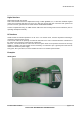
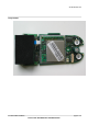
Examples
OM-Gryphon