DS4300 INSTALLATION MANUAL
We DATALOGIC S.p.A. Via Candini, 2 40012 - Lippo di Calderara Bologna - Italy declare under our sole responsibility that the product DS4300-XXXX, Laser Scanner and all its models to which this declaration relates is in conformity with the following standards or other normative documents EN 55022, August 1994: LIMITS AND METHODS OF MEASUREMENTS OF RADIO DISTURBANCE CHARACTERISTICS OF INFORMATION TECHNOLOGY EQUIPMENT (ITE) EN 50082-2, March 1995: ELECTROMAGNETIC COMPATIBILITY. GENERIC IMMUNITY STANDARD.
CONTENTS GUIDE TO INSTALLATION ...............................................................v General View ..................................................................................... vi SAFETY PRECAUTIONS ................................................................viii Laser Safety......................................................................................viii Standard Regulations .......................................................................viii Power Supply..............
3 3.1 3.1.1 3.2 3.2.1 3.2.2 3.3 3.4 READING FEATURES ....................................................................3.1 Advanced Code Reconstruction ......................................................3.1 Tilt Angle for Advanced Code Reconstruction.................................3.2 Decoding Capacity in Linear Mode ..................................................3.3 Step Ladder Mode ...........................................................................3.3 Picket Fence Mode ..................
GUIDE TO INSTALLATION The following can be used as a checklist to verify all of the steps necessary for complete installation of the DS4300 scanner. 1) Read all information in the section "Safety Precautions" at the beginning of this manual. 2) Correctly position and mount the scanner for barcode reading according to the information in paragraphs 2.2, 2.5 and 3.4. 3) Provide correct system cabling according to the signals necessary for your application (see the applicable sub-paragraphs under 2.3 or 2.4).
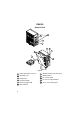
DS4300 General View 11 10 9 8 6 4 2 1 5 7 3 Figure A 1 Cable with 25-pin connector 7 Warning and Classification labels 2 Mounting holes Ready LED 8 9 Laser active LED 5 Good Read LED External Trigger LED 10 Laser beam output window 11 Accessory mounting holes 6 Data TX LED 3 4 vi Warning Label
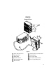
DS4300 General View 11 10 9 8 6 2 5 4 7 3 1 Figure B 1 Cable with junction box 7 Warning and Classification labels 2 Mounting holes 8 9 Warning Label Laser active LED 3 Ready LED 4 Good Read LED 5 External Trigger LED 6 10 Laser beam output window 11 Accessory mounting holes Data TX LED vii
SAFETY PRECAUTIONS LASER SAFETY The following information is provided to comply with the rules imposed by international authorities and refers to the correct use of the DS4300 scanner. Standard Regulations This scanner utilizes a low-power laser diode. Although staring directly at the laser beam momentarily causes no known biological damage, avoid staring at the beam as one would with any very strong light source, such as the sun.
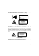
Warning labels indicating exposure to laser light and the device classification are applied onto the body of the scanner (Figure A/B, 8 and 7 ). DATALOGIC S.p.A. Via Candini, 2 40012 LIPPO DI CALDERARA (BO) ITALY Model No. Serial No. Volt Amp. Manufactured This product conforms to the applicable requirements of 21CFR1040 at the date of manufacture.
POWER SUPPLY For Model DS4300-1000: This device is intended to be supplied by a UL Listed Direct Plug-In Power Unit marked "Class 2", output rated 10-30 V, minimum 0.55 A. This device may also be supplied by a UL Listed Power Unit with a "Class 2" or LPS power source which supplies power directly to the scanner via the 25-pin connector. For Model DS4300-1001: This device is intended to be supplied via the Junction Box by an NEC Class 2 Power Source, rated 10-30 V, minimum 0.55 A.
DATALOGIC DS4300 1 GENERAL FEATURES 1.1 INTRODUCTION The DS4300 is a compact laser scanner complete with decoder which employs Datalogic’s powerful ACR™ (Advanced Code Reconstruction) technology. It was designed to satisfy the most demanding requirements associated with omni-directional scanning, reading of non-oriented barcode labels, and reading of poorly printed or damaged labels. Standard Application Program A Standard Application Program is factory-loaded onto the DS4300.
DS4300 DATALOGIC 1.
DATALOGIC DS4300 Electrical connection is provided through a cable on the side of the reader; this cable is terminated with a 25-pin connector (25-pin connector models, see paragraph 1.3, Figure A, 1 ) or by a junction box (junction box models, see paragraph 1.3, Figure B, 1 ). The laser beam output window is on the right hand side of the scanner (Figure A/B, 10 ). A green LED on the same side indicates the laser is active (Figure A/B, 9 ).
DS4300 DATALOGIC 1.3 AVAILABLE MODELS The DS4300 scanner is available in versions that differ in regard to the following characteristics: • Optical Resolution • Cable Termination The following models are therefore available: DS4300 - 100X Optical Resolution Cable Termination 1 = Standard Resolution 0 = 25-pin connector 1 = junction box 1.
DATALOGIC DS4300 2 INSTALLATION 2.1 PACKAGE CONTENTS Verify that the DS4300 reader and all the parts supplied with the equipment are present and intact when opening the packaging; the list of parts includes: 1) 2) 3) 4) 5) DS4300 reader with cable Installation manual Barcode test chart DS4300 communication and utility program disk Mounting kit • Mounting screws and washers (4 ea.) • Mounting bracket (1) * Junction box (for junction box models only, see paragraph 1.3) 4 3 2 5 * 1 Figure 2.
DS4300 DATALOGIC 2.2 MECHANICAL INSTALLATION DS4300 can be installed to operate in different positions. The four screw holes (M4 x 5) on the body of the reader are for mechanical fixture (Figure A/B, 2 ). The diagram below gives the overall dimensions of the scanner and may be used for its installation. Refer to paragraph 2.5 for correct positioning. Figure 2.2 - Overall dimensions 2.
DATALOGIC DS4300 2.3 JUNCTION BOX INSTALLATION The junction box provides a passive connection between your scanner and the outside world in a fast and practical way. It represents an alternative to the 25-pin connector models. Figure 2.3 shows the basic layout of DS4300 using the junction box. Scanner cable Junction Box DS4300 System cables Figure 2.
DS4300 DATALOGIC The junction box is designed to be mounted to a panel of metal, plastic or other appropriate material using the mounting screws provided in the package. To do this: 1) Open the junction box by unscrewing the 4 cover screws. If necessary, using the two mounting holes inside the junction box as a pattern, mark the panel with an appropriate object and then drill two small pilot holes in the panel.
DATALOGIC DS4300 2.3.2 Junction Box Electrical Connections The connection and wiring procedure for the junction box is described as follows: 1) Open the junction box by unscrewing the 4 cover screws. 2) Pass all System cables through the glands in the junction box housing. 3) To connect the power and input/output signals: • Prepare the individual wires of the system cables by stripping the insulation back approximately 11 mm.
DS4300 DATALOGIC J. BOX pinout for DS4300 Pin Name 01 02 03 04 05 06 07 08 09 10 11 12 13 14 15 16 17 18 19 20 21 22 23 *24 *25 *26 27 28 29 30 31 32 33 34 35 36 37 38 39 VS GND VS GND CHASSIS VS VS EXT TRIG+ EXT TRIGGND GND VS VS IN1+ IN1GND GND OUT1+ OUT1OUT2+ OUT2IN2+ IN2Main interface signals see table below Reserved GND Main interface signals see table below 18 J1 39 1 5 17 Figure 2.
DATALOGIC DS4300 4) After wiring the junction box and while the scanner is unplugged from the power supply, place the Scanner cable so that the rubber seal fits into the cutout in the housing of the junction box and plug the 24-pin connector into connector J1 on the PCB inside the junction box as shown in figure 2.9. Rubber seal J1 Scanner cable Figure 2.
DS4300 DATALOGIC 2.4 ELECTRICAL CONNECTIONS FOR 25-PIN MODELS 25-pin connector models (see paragraph 1.3) are equipped with a cable terminated by a 25-pin D-sub connector for connection to the power supply and input/output signals. The details of the connector pins are indicated in the following table: Figure 2.
DATALOGIC DS4300 2.4.1 Power Supply Power can be supplied to the scanner through the pins provided on the 25pin connector used for communication with the host (Figure 2.11): USER INTERFACE DS4300 13 VS V+ (10 - 30 Vdc) 25 GND GND CHASSIS 1 Earth Ground CHASSIS Figure 2.11 - Power supply connections or through the jack connector on the side of the 25-pin connector for connections to a UL Listed Direct Plug-in Power Unit (Figure 2.12).
DS4300 DATALOGIC 2.4.2 Main Serial Interface The signals relative to the following serial interface types are available on the input/output connector: RS232 RS485 FULL DUPLEX RS485 HALF DUPLEX An active 20-mA Current Loop interface is available if the optional INT-24 accessory is installed. This accessory interface replaces the RS232/RS485 selections. The main serial interface type and its relative parameters (baud rate, data bits, etc.
DATALOGIC DS4300 DS4300 USER INTERFACE 2 TX232 3 RX232 4 RTS232 5 CTS232 7 SGND Main RXD TXD DCD DTR SGND RTS/CTS HARDWARE HANDSHAKING ENABLED Figure 2.13 - RS232 main interface connections Figure 2.14 - RS232 control signals The RTS232 and CTS232 signals control data transmission and synchronize the connected devices. If the RTS/CTS handshaking protocol is enabled, the DS4300 activates the RTS232 output to indicate a message is to be transmitted.
DS4300 DATALOGIC RS485 Full-Duplex The RS485 full-duplex interface is used for non-polled communication protocols in point-to-point connections over longer distances than those acceptable for RS232 communications or in electrically noisy environments.
DATALOGIC DS4300 RS485 Half-Duplex The RS485 half-duplex (3 wires + shield) interface is used for polled communication protocols. It can be used for Multidrop connections in a master/slave layout or with a Datalogic Multiplexer, (see par. 2.6.4 and 2.6.5).
DS4300 DATALOGIC The figure below shows a multidrop configuration with DS4300 scanners connected to a Multiplexer. max. 2 m. 1 DS4300 2 #x 4 (up to 31) 7 DS4300 2 #1 4 1 CHASSIS 120 Ohm 7 DS4300 2 #0 4 1 max. 1200 m. RTX485+ RTX485SGND Main 7 three wires + shield RTX485+ MULTIPLEXER RTX485RS485REF SHIELD 120 Ohm Figure 2.17 - DS4300 multidrop connection to a Multiplexer 2.
DATALOGIC DS4300 20 mA Current Loop (INT-24 Accessory Only) When the INT-24 accessory board is installed, the DS4300 is equipped with a 20 mA active current loop interface. The following pins of the 25-pin connector are used for the connections: Pin 4 5 7 Name CLOUTCLINSGND Main Function current loop output current loop input signal ground main interface DS4300/DS4600 USER INTERFACE + I = 20 mA 4 C.L. OUT- 7 SGND Main 5 C.L. IN- + I = 20 mA GND MAX. 300 METERS Figure 2.18 - 20 mA active C.
DS4300 DATALOGIC 2.4.3 Auxiliary RS232 Interface The auxiliary serial interface is used exclusively for RS232 point-to-point connections. The parameters relative to the auxiliary interface (baud rate, data bits, etc.) as well as particular communication modes such as Local Echo can be defined using the WinHost utility program or Host Mode programming. For more details refer to paragraph 2.6 and to the section "Auxiliary Interface Menu" in the WinHost Help On Line.
DATALOGIC DS4300 The pinouts are indicated below: Pin 18 19 6 10 14 15 Name EXT TRIG+ EXT TRIGIN1+ IN1IN2+ IN2- Function external trigger + external trigger input 1 + input 1 input 2 + input 2 - The EXT TRIG inputs are used in the ON-Line Operating mode and tells the scanner to scan for a code. The active state of this input is selected in software. Refer to the WinHost Help On Line. The yellow led, (Figure A/B, 5 ), is on when the External Trigger signals the active reading phase.
DS4300 DATALOGIC Vext 30 Vdc max. USER INTERFACE DS4300 V + 5V 18/6/14 + 19/10/15 - Signal Ground Figure 2.22 - Input PNP command using external power DS4300 USER INTERFACE 9 VS + 5V 18/6/14 + 19/10/15 - 25 V Signal GND Figure 2.23 - Input PNP command using DS4300 power The electrical features of the inputs are: Maximum voltage = 30 Vdc Maximum current = 25 mA. An anti-disturbance hardware filter is implemented on the External Trigger input (< 5 milliseconds delay).
DATALOGIC DS4300 2.4.5 Outputs The following pins are present on the 25-pin connector of the scanner: Pin 8 22 11 12 Name OUT1+ OUT1OUT2+ OUT2- Function output 1 + output 1 output 2 + output 2 - The meaning of the two outputs OUT1 and OUT2 can be defined by the user (No Read, Right or Wrong). Refer to WinHost Help On Line. By default, OUT1 is associated with the No Read event, which activates when the code signalled by the External Trigger is not decoded.
DS4300 DATALOGIC 2.5 POSITIONING The DS4300 scanner is able to decode moving barcode labels at a variety of angles, however significant angular distortion may degrade reading performance. When mounting the DS4300 take into consideration these three ideal label position angles: Pitch 0°, Skew 10° to 30° and Tilt 0°. Follow the suggestions below for the best orientation: P The Pitch angle is represented by the value P in figure 2.25. Position the reader in order to minimize the Pitch angle. Figure 2.
DATALOGIC DS4300 2.6 TYPICAL LAYOUTS The following typical layouts refer to system hardware configurations. Dotted lines in the figures refer to optional hardware configurations within the particular layout. These layouts also require the correct setup of the software configuration parameters. Complete software configuration procedures can be found in the Guide To Rapid Configuration in the WinHost Help On Line. 2.6.
DS4300 DATALOGIC 2.6.2 Pass Through Pass through mode allows two or more devices to be connected to a single external serial interface. Each DS4300 transmits the messages received by the auxiliary interface onto the main interface. All messages will be passed through this chain to the host. When On-Line Operating mode is used, the scanner is activated by an External Trigger (photoelectric sensor) when the object enters its reading zone.
DATALOGIC DS4300 2.6.3 RS232 Master/Slave The RS232 master/slave connection is used to collect data from several scanners to build either an omni-directional or a multi-sided reading system; there can be one master and up to 9 slaves connected together. The Slave scanners use RS232 only on the main and auxiliary serial interfaces. Each slave DS4300 transmits the messages received by the auxiliary interface onto the main interface. All messages will be passed through this chain to the Master.
DS4300 DATALOGIC 2.6.4 RS485 Master/Slave The RS485 master/slave connection is used to collect data from several scanners to build either an omni-directional or a multi-sided reading system; there can be one master and up to 5 slaves connected together. The Slave scanners are connected together using RS485 half-duplex on the main serial interface. Every Slave scanner must have a multidrop address in the range 0-4. The Master scanner is also connected to the Host on the RS232 auxiliary serial interface.
DATALOGIC DS4300 NOTE The auxiliary serial interface of the slave scanners can be used in Local Echo communication mode to control any single scanner (visualize collected data) or to configure it using the WinHost utility or Host Mode Programming procedure. The termination resistors of the RS485 bus must not be installed. 2.6.5 Multiplexer Each scanner is connected to an MX4000 with the RS485 half duplex mode on the main interface.
DS4300 DATALOGIC This page is intentionally left blank. 2.
DATALOGIC DS4300 3 READING FEATURES 3.1 ADVANCED CODE RECONSTRUCTION The traditional way of barcode reading could be called "Linear Reading". In this case, the laser beam crosses the barcode symbol from its beginning to its end as shown in Figure 3.1. Laser Beam Figure 3.1 - Linear reading In “Advanced Code Reconstruction” mode, it is no longer necessary for the laser beam to cross the label from the start to the end.
DS4300 DATALOGIC 3.1.1 Tilt Angle for Advanced Code Reconstruction The most important parameter in Advanced Code Reconstruction is the value of the maximum tilt angle (α maximum) under which the code reconstruction process is still possible. We define the Tilt angle as the angle (α) between the laser beam and a line parallel to the barcode label, as shown in Figure 3.3. Laser Beam 0° to α max α = tilt angle α Figure 3.
DATALOGIC DS4300 3.2 DECODING CAPACITY IN LINEAR MODE When in Linear Reading mode, the number of reads performed by the DS4300 and therefore the decoding capacity, is influenced by the following parameters: • number of scans per second • code motion speed • label dimensions • scan direction with respect to code motion At least 5 scans during the code passage should be allowed to ensure a successful read. 3.2.1 Step Ladder Mode Code motion moving at LS speed DS4300 LH Laser Beam Figure 3.
DS4300 DATALOGIC For example, the DS4300 (800 scans/sec.), for a 25 mm high code moving at 1250 mm/s performs: [(25/1250) * 800] - 2 = 14 effective scans. 3.2.2 Picket Fence Mode Laser Beam Code motion moving at LS speed DS4300 LW FW Figure 3.6 - "Picket Fence" scanning mode If scanning is parallel to the code motion, (Figure 3.
DATALOGIC DS4300 3.3 PERFORMANCE The DS4300 scanner reads codes with densities from 0.20 mm (8 mils) to 1.00 mm (40 mils) in the zone between 50 mm (1.9 in) and 400 mm (15.7 in) from the emission window. DS4300 can be optimized for reading high density codes (between 0.20 mm (8 mils) and 0.30 mm (12 mils) by configuring the Code Resolution parameter (see WinHost Help On Line). Refer to the diagrams given in paragraph 3.4 for further details on the reading features.
DS4300 DATALOGIC 3.4 READING DIAGRAMS The following diagrams show the reading distance for barcodes with different densities. DS4300-100X (Code Resolution Standard) 0.50 mm (20 mils) 0.60 mm (24 mils) ≥ 0.80 mm (31 mils) NOTE: (0,0) is the center of the laser beam output window CONDITIONS: Test Codes used "Pitch" angle "Skew" angle "Tilt" angle Reading Mode Code Resolution 3.
DATALOGIC DS4300 DS4300-100X (Code Resolution High) 0.20 mm (8 mils) 0.30 mm (12 mils) NOTE: (0,0) is the center of the laser beam output window CONDITIONS: Test Codes used "Pitch" angle "Skew" angle "Tilt" angle Reading Mode Code Resolution = Interleaved 2/5 and Code 39 (according to the Datalogic Barcode Test Chart) = 0° = 10° = 0° = Linear = High Reading Features - 3.
DS4300 DATALOGIC This page is intentionally left blank. 3.
DATALOGIC DS4300 4 MAINTENANCE 4.1 CLEANING Clean the laser beam output window periodically for continued correct operation of the reader. Dust, dirt, etc. on the window may alter the reading performance. Repeat the operation frequently in particularly dirty environments. Use soft material and alcohol to clean the window and avoid any abrasive substances. WARNING Clean the window of the DS4300 when the scanner is turned off or, at least when the laser beam is deactivated. Maintenance - 4.
DS4300 DATALOGIC This page is intentionally left blank. 4.
DATALOGIC DS4300 5 TECHNICAL FEATURES ELECTRICAL FEATURES Power Supply voltage Power consumption max. Serial Interfaces Main 10 to 30 Vdc 5.5 W RS232, RS485 full-duplex, RS485 half-duplex (20 mA C.L. only with INT-24 accessory ) Auxiliary Baud rates Inputs Voltage max. Input current max. Outputs VCE max. Collector current max. VCE saturation Power dissipation max.
DS4300 DATALOGIC SOFTWARE FEATURES READABLE CODE SYMBOLOGIES • EAN/UPC • Code 93 • 2/5 Interleaved • Code 128 • Code 39 • EAN 128 • Codabar • Pharmacode CODE SELECTION up to six codes during one reading phase DECODING SAFETY can enable multiple good reads of same code HEADERS AND TERMINATORS up to four headers and four terminators OPERATING MODES ON LINE, AUTOMATIC, SERIAL ON LINE, TEST CONFIGURATION MODES • through menus using WinHost utility • receiving commands from one of the serial p