Datalogic Jet™ www.mobile.datalogic.com World wide Sales Network available from: www.mobile.datalogic.com/contacts Datalogic Mobile S.r.l. Via S. Vitalino, 13 40012 Lippo di Calderara di Reno Bologna - Italy Telephone: (+39) 051-3147011 Fax: (+39) 051-3147561 User’s Manual ©2004-2007 Datalogic Mobile S.r.l. 822000645 (Rev.
Datalogic Mobile S.r.l. Via S. Vitalino 13 40012 - Lippo di Calderara di Reno Bologna - Italy Datalogic Jet™ - User's Manual Ed.: 11/2007 ALL RIGHTS RESERVED Datalogic reserves the right to make modifications and improvements without prior notification. Datalogic shall not be liable for technical or editorial errors or omissions contained herein, nor for incidental or consequential damages resulting from the use of this material.
CONTENTS REFERENCES ............................................................................................. v Conventions .................................................................................................. v Reference Documentation ............................................................................ v Services and Support.................................................................................... v SAFETY REGULATIONS.......................................................
3.4.3 3.5 3.5.1 3.5.2 3.6 3.6.1 3.6.2 3.7 3.7.1 3.7.2 3.7.3 3.7.4 3.7.5 3.7.6 3.8 3.8.1 3.8.2 3.8.3 3.9 Key Selection .............................................................................................. 25 Status Indicators ......................................................................................... 31 LED Status.................................................................................................. 31 Taskbar ................................................................
REFERENCES CONVENTIONS This manual uses the following conventions: “User” refers to anyone using a Datalogic Jet™ PDA. “PDA” and " Datalogic Jet™" refer to Datalogic Jet™ PDA. “You” refers to the System Administrator or Technical Support person using this manual to install, configure, operate, maintain or troubleshoot a Datalogic Jet™ PDA. REFERENCE DOCUMENTATION For further information regarding Datalogic Jet™ refer to the SDK Help on-Line.
SAFETY REGULATIONS NOTE Read this manual carefully before performing any type of connection to the Datalogic Jet™ PDA. The user is responsible for any damages caused by incorrect use of the equipment or by inobservance of the indication supplied in this manual. GENERAL SAFETY RULES − Use only the components supplied by the manufacturer for the specific Datalogic Jet™ PDA being used. − Do not attempt to disassemble the Datalogic Jet™ PDA, as it does not contain parts that can be repaired by the user.
LASER SAFETY The laser light is visible to the human eye and is emitted from the window indicated in the figure. This information applies to both Laser models and the Datalogic Jet™ Imager Aiming System. Laser output window This product complies with 21 CFR Subchapter J AVOID EXPOSURE LASER LIGHT IS EMITTED FROM THIS APERTURE LASER LIGHT - DO NOT STARE INTO BEAM CLASS 2 LASER PRODUCT MAX. OUTPUT RADIATION 1.
ENGLISH The following information is provided to comply with the rules imposed by international authorities and refers to the correct use of your PDA. STANDARD LASER SAFETY REGULATIONS This product conforms to the applicable requirements of both CDRH 21 CFR 1040 and EN 60825-1 at the date of manufacture. For installation, use and maintenance, it is not necessary to open the device.
DEUTSCH Die folgenden Informationen stimmen mit den Sicherheitshinweisen überein, die von internationalen Behörden auferlegt wurden, und sie beziehen sich auf den korrekten Gebrauch vom PDA. NORM FÜR DIE LASERSICHERHEIT Dies Produkt entspricht am Tag der Herstellung den gültigen EN 60825-1 und CDRH 21 CFR 1040 Normen für die Lasersicherheit. Es ist nicht notwendig, das Gerät wegen Betrieb oder Installations-, und WartungsArbeiten zu öffnen.
ESPAÑOL Las informaciones siguientes son presentadas en conformidad con las disposiciones de las autoridades internacionales y se refieren al uso correcto del PDA. NORMATIVAS ESTÁNDAR PARA LA SEGURIDAD LÁSER Este aparato resulta conforme a las normativas vigentes de seguridad láser a la fecha de producción: CDRH 21 CFR 1040 y EN 60825-1. No es necesario abrir el aparato para la instalación, la utilización o la manutención.
The following shows the correspondence between the Datalogic Jet™ models and the Radio modules: DLBJET™ 5XX-XXX-XXX 802.11b (Wi-Fi) radio card DLBJET ™ 7XX-XXX-XXX 802.11b/g (Wi-Fi) radio card DLBJET ™ X1X-XXX-XXX GSM/GPRS Tri-band (900, 1800, 1900 MHz) module Information for the User ENGLISH Contact the competent authority responsible for the management of radio frequency devices of your country to verify any possible restrictions or licenses required. Refer to the web site http://europa.eu.
FCC COMPLIANCE Modifications or changes to this equipment without the expressed written approval of Datalogic could void the authority to use the equipment. This device complies with PART 15 of the FCC Rules. Operation is subject to the following two conditions: (1) This device may not cause harmful interference, and (2) this device must accept any interference received, including interference which may cause undesired operation. FCC ID U4G0019. All DLBJET™ 5XX-XXX-XXX Wi-Fi models contain FCC ID H9PLA4137.
WEEE COMPLIANCE Informazione degli utenti ai sensi della Direttiva Europea 2002/96/EC L’apparecchiatura che riporta il simbolo del bidone barrato deve essere smaltita, alla fine della sua vita utile, separatamente dai rifiuti urbani.
éviter les retombées négatives pour l'environnement et la santé dérivant d'une élimination incorrecte récupérer les matériaux dans le but d'une économie importante en termes d'énergie et de ressources Pour obtenir des informations complémentaires concernant l'élimination, veuillez contacter le fournisseur auprès duquel vous avez acheté le produit ou consulter la section consacrée au site Web www.mobile.datalogic.com.
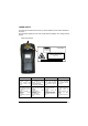
GENERAL VIEW A J B K I C D P O E N H G M F L Figure A – General View A) B) C) D) E) F) G) H) Data capture/Laser output window Scan key(s) (3) Bluetooth® LED Charging status LED Backlit keyboard External power supply connector Communication/Charger connector Headset jack I) J) K) L) M) N) O) P) User programmable LED Backlit display Mini SD card SLOT Microphone Latch release button Battery latch Battery pack Speaker xv
xvi
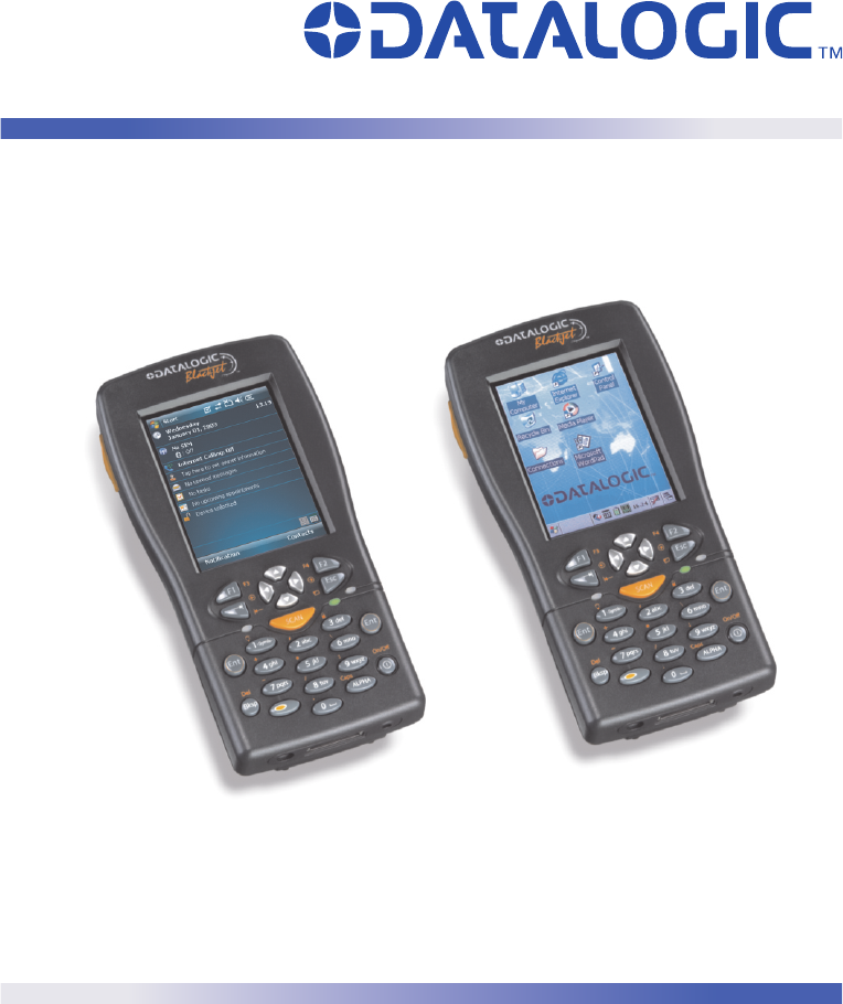
INTRODUCTION 1 1.1 1 INTRODUCTION DATALOGIC JET™ PDA DESCRIPTION The Datalogic Jet™, is the powerful Datalogic PDA. Thanks to the state-of the-art architecture and the most advanced technologies, it can provide the most suitable levels for capturing, computing and communicating data faster and easier.
DATALOGIC JET™ 1 1.2 AVAILABLE MODELS The Datalogic Jet™ PDA is available in different models depending on the options it is equipped with. All options are listed below: • • • communication options: Wi-Fi 802.11b, Wi-Fi 802.11b/g, GSM/GPRS, Bluetooth® capture options: laser, imager, laser + RFID compute options (fixed): O.S. version, microprocessor type/speed, memory size For further details about the Datalogic Jet™ PDA models refer to the web site: www.mobile.datalogic.com. 1.
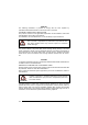
INTRODUCTION 1.4 1 INSERTING MINI SD CARD With Datalogic Jet™ PDA, it is possible to add a Mini SD Card for additional storage capacity. To access the Mini SD card slot, unscrew the cover at the side of Datalogic Jet (see Figure A) and then proceed as follows: 1. Before inserting the Mini SD card, peel the adhesive pull tab and stick it onto to the Mini SD card as shown in the picture below: 2. Open the Mini SD card slot by unscrewing the two screws: 3.
1 CAUTION 4 DATALOGIC JET™ Follow proper ESD precautions to avoid damaging the SD. Proper ESD precautions include, but are not limited to, working on an ESD mat and ensuring that the operator is properly grounded. Do not force the card. If you feel resistance, remove the card, check the orientation, and reinsert it. Do not use the SD card slot for any other accessories.
INTRODUCTION 1.5 1 ACCESSORIES Cradles 94A151096 Datalogic Jet™ Single Cradle Desk (includes slot for spare battery pack recharge; RS232 and USB communications) 94A151097 Jet™ Vehicle Cradle Loudspeaker 94A151100 Jet™ Vehicle Cradle Standard Charger 94A151098 Datalogic Jet™ Multi-Battery pack Charger (4 slots) Batteries 94ACC1293 Datalogic Jet™ Standard Battery pack (Li-Ion battery pack 1070 mAh@7.4 V) 94ACC1294 Datalogic Jet™ Large Capacity Battery pack (Li-Ion battery pack 1800 mAh@7.
DATALOGIC JET™ 1 NOTE 1.6 Use only a Datalogic Mobile-approved power supply and cables. Use of an alternative power supply will invalidate any approval given to this device and may be dangerous. OPERATING SYSTEM Datalogic Jet™ comes in two different models, respectively supporting Windows CE and Windows Mobile. For further information regarding Windows Mobile refer to the website: http://www.microsoft.com/windowsmobile.
CONNECTIONS 2 2 CONNECTIONS 2.1 PDA CONNECTION TO THE HOST COMPUTER 2.1.1 RS232/USB Direct Connection You can use a cable to connect the Datalogic Jet™ PDA to a host computer to transfer data.
DATALOGIC JET™ 2 2.1.2 WLAN Connection Datalogic Jet™ Wi-Fi 802.11b and Wi-Fi 802.11b/g1 models can communicate with the host using the on-board radio frequency module and an Access Point connected to the host computer. For models using the WiFi7 radio (7xx-xxx-xxx models), you can find information about the applet for radio configuration: http://www.summitdatacom.com/SCU.htm. To launch this utility you can tap the specific icon if it’s visible on the taskbar or: 1.
CONNECTIONS NOTE NOTE NOTE 2 Wi-Fi module is on by default. In order to avoid wasting energy, you can switch it off using the Wireless Communications applet (see par. 3.7.4). To start configuring your WLAN connection, tap the Wi-Fi icon at the bottom of the screen. Suspending the terminal powers off the 802.11b/g radio and drops the radio connection. When the terminal resumes, depending on the radio power mode and security protocol selected, it takes approximately from 10 to 30 seconds for the 802.
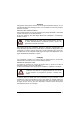
DATALOGIC JET™ 2 2.1.3 WPAN Connection Datalogic Jet™ PDAs can communicate with a Bluetooth® device, such as a printer, ® within a range of 10 m, using the on-board Bluetooth module. A B Key: A) Datalogic Jet™ PDA B) Bluetooth® printer NOTE In order to avoid wasting energy, the Bluetooth® module is off by default. If you need to have Bluetooth® working, the module must be powered on using the Wireless Communications applet (see par. 3.7.4), and perform the Discovery procedure (see par. 3.8.2).
CONNECTIONS 2 Area coverage and Bluetooth radio performance may vary, due to environmental conditions or interference caused by other devices (microwave ovens, radio transmitters, etc.), etc.
DATALOGIC JET™ 2 2.1.4 WWAN Connection Datalogic Jet™ GSM/GPRS models enhance your connectivity solutions giving you an opening to an international wireless infrastructure that is the standard in Europe and Asia. GSM (Global System for Mobile communications) is a digital mobile phone system based on TDMA; it utilizes the 900, 1800 and 1900 MHz bands. GPRS supports IP (Internet Protocol) and allows accessing Internet and Intranet services, such as sending and receiving e-mail or Web browsing.
CONNECTIONS 2 13
DATALOGIC JET™ 2 Installing the SIM Card To correctly insert the SIM Card, proceed as follows: 1- Turn off the Datalogic Jet™ PDA.
CONNECTIONS 2 4- Open the Sim Card slot by pulling up the locking plate. 5- Pull up the cardholder and insert the Sim Card with its contacts downward and its round corner at the bottom. 6- Lock the card into place by pushing the cardholder down and then pulling the locking plate down.
DATALOGIC JET™ 2 CAUTION Follow proper ESD precautions to avoid damaging the SIM card. Proper ESD precautions include, but are not limited to, working on an ESD mat and ensuring that the operator is properly grounded. Do not force the card. If you feel resistance, remove the card, check the orientation, and reinsert it. Do not use the SIM card slot for any other accessories. Removing the SIM Card To remove the SIM card, follow the steps above to access the SIM area, and remove it from its slot.
CONNECTIONS 2.2 2 CONNECTION CABLES The following cables are listed with their order number.
DATALOGIC JET™ 3 3 USE AND FUNCTIONING The use of the Datalogic Jet™ PDA depends on the application software loaded. However there are several parameters that can be set and utilities that can be used to perform some basic functions such as data capture, communications, file management, etc. 3.1 PDA STARTUP The Datalogic Jet™ PDA turns on when the battery pack or the external supply is inserted. After the battery pack is installed, use the [ON/OFF] key to turn the PDA on and off.
USE AND FUNCTIONING 3 When it is no longer used for more than a programmable timeout, which is defined in the POWER applet of the Control Panel, the PDA goes into power-off (low power with display and keyboard backlight off). In this mode it can be awakened (resuming operation) by the [ON/OFF] key. The PDA can also be awakened or turned off by the application program. NOTE 3.2 USING THE STYLUS The stylus selects items and enters information. The stylus functions like a mouse.
DATALOGIC JET™ 3 Use only original Datalogic styluses supplied with the product itself. CAUTION In harsh applications, use of should be taken into consideration, in touch screen operating life. screen order to protectors extend the To prevent damage to the screen, do not use sharp devices or any device other than the Datalogic Mobile-provided stylus. Do not apply not necessary high pressures on the screen.
USE AND FUNCTIONING 3.3 3 DATA CAPTURE To capture data, first of all select the barcode icon on the bottom-right side of the display and tap the 'Capture' menu item, then proceed with the following directions. To configure and enable data capture parameters refer to par. 3.6. 3.3.1 Laser Data Capture To scan barcodes, point the Datalogic Jet™ PDA laser model onto the code from a distance within the reading range while pressing one of the three SCAN Keys. See the reading diagrams in par. 5.
DATALOGIC JET™ 3 3.3.2 Imager Data Capture To read a 1D or 2D code, simply point the Datalogic Jet™ Imager model onto the code from a distance within the reading range (see par. 5.1, section Datalogic Jet™ Imager Optical Features) and press one of the three SCAN Keys.
USE AND FUNCTIONING Linear barcode 3 2D Matrix symbol ÌBX3ÉÎ Relative Size and Location of Aiming System Pattern The field of view changes its size as you move the reader closer or farther away from the code. The field of view indicated by the aiming system pattern will be smaller when the Datalogic Jet™ Imager is closer to the code and larger when it is farther from the code. Symbologies with smaller bars or elements (mil size) should be read closer to the unit.
DATALOGIC JET™ 3 3.4 DESCRIPTION OF THE KEYS The Datalogic Jet™ PDA provides a function-oriented keyboard having a total of 27 keys. The keyboard can be divided as follows: 2 Lateral SCAN keys (1 per side) System Control and Navigation Keys Power Key General keys 3.4.1 System Control and Navigation Keys Powers the PDA ON or OFF. They let you move forwards or backwards within the Internet Explorer browser pages.
USE AND FUNCTIONING 3.4.
DATALOGIC JET™ 3 Some of these keys carry extra symbols and are logically divided in up to 3 sections according to the following figure: A B C Each section corresponds to a symbol that can be obtained using the corresponding keyboard method according to the following scheme: A) function of the key when simultaneously pressed along with the Orange key; B) function of the key when directly pressed; C) function of the key when in Alpha mode, in order to digit all the alphabetic characters positioned over
USE AND FUNCTIONING 3 Switches on/off the keyboard backlight. Both display and keyboard backlight automatically turn off after a timeout, depending on Control Panel settings. The backlights automatically turn off after a set timeout. Once the Alpha mode has been entered, press the Alpha key again to exit this mode.
DATALOGIC JET™ 3 3.4.3 Resetting the Jet Windows CE There are several reset methods for the Jet. A warm boot terminates an unresponsive application and clears the working RAM, but preserves both the file system and the registry. A cold boot forces all applications to close and clears the working RAM and the files not resident on the persistent flash memory. Registry is restored from persistent memory if available or returned to factory default.
USE AND FUNCTIONING 3 To perform a clean boot, follow these steps: 1. 2. 3. 4. 5. Perform a Cold Boot (see Cold Boot). Quickly release all the keys when the screen goes black. Within 1 second press and hold down the Esc and 0 keys until the left orange led starts blinking. Release the Esc and 0 keys. Enter 1 to proceed with the Clean Boot sequence. Enter 0 to cancel the Clean Boot and proceed with a Cold Boot.
DATALOGIC JET™ 3 Cold Boot A cold boot is a complete reset of the Jet in which all applications are forcibly closed and the RAM is completely cleared. Registry is restored from persistent memory if a saved copy is available (see Registry Applet, par. 3.7.2). Applications and data stored on file system are preserved. A cold boot is necessary when the Windows Mobile operating system locks up and the warm boot command does not work.
USE AND FUNCTIONING 3.5 3.5.1 3 STATUS INDICATORS LED Status The Datalogic Jet™ provides three different LEDs signaling the PDA status. LED STATUS General Purpose (left-side) Green/Red This LED is available to the application program. Blue blinking Bluetooth® (extreme right -side) It blinks when the Bluetooth® module is on. Charging Status (right side) Green constant It is constant once the charging process has been completed. Red blinking It blinks when the battery pack is running down.
DATALOGIC JET™ 3 3.5.2 Taskbar As well as tasks opened in Windows, the Taskbar provides several status icons that report information about the time, the battery level, the keyboard function, and the decoding status. ICONS DESCRIPTION Time and Battery Icons It shows the time. In Windows CE, they are representative of five different icons indicating the battery level. The icon is green or red colored according to the power left (green when >20%, red when <20%).
USE AND FUNCTIONING 3 Windows CE Taskbar Windows Mobile Taskbars 33
DATALOGIC JET™ 3 3.6 DATA CAPTURE CONFIGURATION From the Windows CE Taskbar, tap the "Data Capture" icon to open a drop–down menu. Data Capture can also be accessed from the Control Panel. By selecting the Info item from this drop-down menu you can access information about the Scanner and the Software; the Configure item opens the configuration applet (Data Capture Configuration Window), while Capture accesses the data capture applet (Data Capture Window), which enables code reading.
USE AND FUNCTIONING 3 The Scan Parameters are common to all scanner modules and allow control of the scanning device (i.e. beeper control, LED control, laser timeout, etc.). Each Data Capture screen window corresponds to a branch of the tree, and the name of the current branch is displayed at the bottom of each screen window. Data Capture Configuration Window The screen format shows two columns where the left column indicates branches or parameters. Branches have three dots in the right column (...).
DATALOGIC JET™ 3 Selecting Data Capture Setup Parameters Alternatively using the stylus, you can tap once directly on the value on the right column; continue tapping until the desired value is reached. To activate a new configuration select the File ->Save Menu to send the new configuration to the barcode decoding software and save the new configuration. This will save the configuration to non-volatile memory preventing loss at the next system reset.
USE AND FUNCTIONING 3 ContinuousMode: when enabled, the scanner can only be turned off by releasing the SCAN key, or if Soft Trigger is enabled, by the application program. Continuous Mode overrides Scan Timeout. KeyboardEmulation: if enabled all scanned data are transformed into keyboard events and can therefore be displayed and saved to a file as if input from the PDA keyboard. If set to “Yes (Clipboard)”, it copies the scanned data to the system clipboard.
DATALOGIC JET™ 3 Default Settings The following tables contain the default values for the major barcode setup parameters, according to the type of scan engine mounted on the PDA. For a complete list of parameters and of their configuration procedures, please refer to the SDK Help file on the CD.
USE AND FUNCTIONING BARCODE SYMBOLOGY SPECIFIC READER PARAMETERS MSI Plessey Code 93 Code 11 PDF - 417 Data Matrix QR POSTNET PLANET Japan Post Australia Post KIX Code Royal Mail Code (RM4SCC) 3 HP Laser Enabled Disabled Disabled Disabled Imager RFID+Laser Disabled Enabled Disabled Enabled Enabled Enabled Disabled* *These codes may be enabled individually but are disabled as a group. RFID SYMBOLOGY PARAMETERS Data Type Read Type RFID+Laser I.
DATALOGIC JET™ 3 3.6.2 Capture The Data Capture applet (Capture) enables code reading. Data Capture Window Data Capture can also be enabled through the Configuration applet by selecting File ->Scanner from the main menu, or by enabling the parameter Scan Always On in the Scan Parameters branch.
USE AND FUNCTIONING 3.7 3 CONTROL PANEL From the Windows CE Desktop, double tap on the "Control Panel" icon to open the Windows CE control panel main window. The Control Panel can also be launched from Start ->Settings ->Control Panel. APPLET programs are displayed as icons; one icon corresponds to each APPLET. Windows CE Control Panel From the Windows Mobile Start menu, tap Settings. A three tab dialog opens: Personal, System, Connections.
DATALOGIC JET™ 3 3.7.1 Buttons The BUTTONS Applet allows assigning desired applications to be launched by one of the function keys (F1, F2, F3, F4). Windows CE Buttons Icon Windows Mobile Buttons Icon On a Windows Mobile unit the user is also able to assign a shortcut to a function key.
USE AND FUNCTIONING 3 Select the “Enable Multipress” check box to enable multipress text input mode. To enables F5, F6, F7, F8, F9, F10 function keys, you need to change the ORANGE key mapping. Select the “F5-F10” check box: Windows CE Windows Mobile If pressed along with keys [5 jkl], [6 mno], [7 pqrs], [8 tuv], [9 wxyz], [0 ], the ORANGE key now enables F5, F6, F7, F8, F9, F10 function keys.
DATALOGIC JET™ 3 3.7.2 Registry The REGISTRY ADMIN applet provides management of Windows CE/ Windows Mobile registry. From the Windows CE control panel main window, select the REGISTRY ADMIN applet by double tapping the Registry Admin icon. From the Windows Mobile Start menu, tap Settings -> System ->Registry. Select the REGISTRY ADMIN applet by tapping the Registry Admin icon. The Registry Administration Main window appears.
USE AND FUNCTIONING 3.7.3 3 Files Admin The FILES ADMIN applet enables control of the permanence of files in the Windows CE System Folder. Because Windows Mobile mounts the entire file system in persistent store (rather than using RAM), it provides both users and applications with a reliable storage platform even in the absence of battery power. The FILES ADMIN applet is therefore not necessary.
DATALOGIC JET™ 3 Two activating procedures are available for Safe Setup: - Select an installation file (for example, a .CAB cabinet file) from the Safe Setup mask. Safe Setup First Mask Then select \Windows or a relevant sub-directory in the path box. Then, Safe Setup will recognize the new files and directories present in the \Windows directory, and will copy them to the \Backup\Windows directory. At the next cold boot, these files will be restored (see par. 3.8.3).
USE AND FUNCTIONING 3 Safe Setup Second Mask 47
DATALOGIC JET™ 3 3.7.4 Wireless Communications The WIRELESS COMMUNICATIONS applet provides management of the Wi-Fi ® Card and of the Bluetooth and GSM/GPRS modules. Windows CE Wireless Communications Icon Windows Mobile Connectivity Icon If the PDA supports Windows CE, select the WIRELESS COMMUNICATIONS applet by double tapping the Wireless Communications icon.
USE AND FUNCTIONING 3 If the PDA supports Windows Mobile, the Wireless Manager application manages access to wireless connections. The 'Wireless Manager' is a sort of 'Control Panel' for bluetooth and phone modules. From here it's possible to turn on or off bluetooth and phone radio stacks. Open the Wireless Manager by tapping Start -> Settings -> Wireless Manager, or by tapping the Connectivity icon located at the top of the screen.
DATALOGIC JET™ 3 3.7.5 Ethernet Settings Windows CE Ethernet cradle Datalogic Jet™ can be connected to an Ethernet network by inserting it into the Datalogic Jet™ Ethernet Multi Cradle. NOTE If the PDA supports Windows CE, ethernet communication requires Datalogic Jet™ SW version 5.41 or later. Verify the software version by tapping on Software – Version in the Datalogic default home page. Otherwise, search for the file version.htm under the Windows CE folder.
USE AND FUNCTIONING 3 The LAN icon will appear on the Taskbar indicating the LAN connection status. By double tapping on the LAN icon in the Taskbar, the LANNDS1 applet allows visualizing the TCP/IP information. Other information such as the MAC Address is available by tapping the Details... button. If it is necessary to set static TCP/IP parameters, you must open the LANNDS1 applet from the Network and Dial-up Connections applet in the Control Panel.
3 DATALOGIC JET™ then ensure that the USB/Ethernet Adapter card connects to Work -> go to Start -> Settings -> Connections -> Connections -> Advanced -> Network Cards: 52
USE AND FUNCTIONING 3.7.6 3 Volume Settings From the Windows CE control panel main window, select the VOLUME SETTINGS applet by double tapping the Volume Settings icon. From the Windows Mobile Start Menu, tap Settings -> System -> Volume Settings. Select the VOLUME SETTINGS applet by tapping the Volume Settings icon.
3 - DATALOGIC JET™ GSM: it is automatically activated each time a phone-call is started. It is not available when using the cradle loudspeaker (in this case Current Profile = Cradle). Output Tab It allows setting the volume for each audio profile: The “Master Volume” slider allows setting the volume used by all audio profiles. In addition, it is possible to attenuate the volume for each single profile through the dedicated slider.
USE AND FUNCTIONING 3 Cradle Tab It allows selecting the cradle type and managing the vehicle cradle headset functioning: Two radio buttons allow selecting the type of cradle to be used. Check the “Cradle desk, AC plug or none” radio button, if using a cradle different from the vehicle cradle or an AC adapter plug. If using a vehicle cradle, check the related radio button.
3 DATALOGIC JET™ Do not use the vehicle cradle headset if the headset button is disabled, since it may cause hearing damage.
USE AND FUNCTIONING 3.8 3 WINDOWS CONNECTIONS To connect the PDA to another device (i.e. Host PC) from Windows, several programs are available in the "Connections" folder on the Datalogic Jet™ Desktop. These programs require specific electrical connections in order to function properly. From the Desktop, double tap on the "Connections" folder to open the following window: 3.8.
DATALOGIC JET™ 3 In Windows Mobile before using the ActiveSync follow the directions described in 2.1.1 NOTE Visit the following Microsoft Web site for the latest in updates and technical information: http://www.microsoft.com/windowsmobile/activesync/default.mspx NOTE ActiveSync® Remote NOTE 58 Microsoft® ActiveSync® Remote is no longer supported in Windows CE. For backward compatibility you can download it from the internet. We suggest enabling the FTP Server and connecting to an FTP Client.
USE AND FUNCTIONING 3.8.2 3 Bluetooth® Manager Device Setup Windows CE Bluetooth® Manager Device Setup In order to enable a Bluetooth® device for communication with the Datalogic Jet™ PDA you must perform the discovery procedure and enable the device as follows: 1. ® Place the Bluetooth device within the range of the Datalogic Jet™ PDA (10 meters). 2.
3 3. DATALOGIC JET™ Tap on the “Me” button to enter the related window; then, tap on the “ON” button ® to activate the Bluetooth module. The module activation may be also performed by using the WIRELESS COMMUNICATION applet as described in par. 3.7.4. By tapping on the “HW Details” and “SW Details” buttons, information about the ® PDA Bluetooth hardware and software will be displayed, while the “Enable ® Encryption” button starts encryption of the Bluetooth communication data.
USE AND FUNCTIONING 3 Once the Discovery procedure has been completed, select the desired ® Bluetooth device from the list. It is also possible to digit (12 hexadecimal digits) the Bluetooth® address of the desired device by tapping on the “Add” button. The “Clear” button deletes all discovered devices from the list. 5.
DATALOGIC JET™ 3 Windows Mobile Bluetooth® Manager Device Setup Before turning on Bluetooth®, ensure that the two devices are within close range and that both Bluetooth-enabled devices are discoverable. 1. Tap Start -> Settings -> Connections tab. 2. Tap Bluetooth > Mode 3. Select or clear the “Turn on Bluetooth” check box: By default, Bluetooth® is turned off. If you turn it on, and then turn off your device, Bluetooth® also turns off.
USE AND FUNCTIONING 3 3. Tap the name of the other device, and tap Next: 4. In Passkey, if you want to use a passkey (recommended for enhanced security), enter a alphanumeric passkey between 1 and 16 characters, and tap Next.
3 DATALOGIC JET™ 5. Enter the same passkey on the other device. 6. To give the partnership a more meaningful name, change the name of the device in Name. 7. Tap Finish. You can give a more meaningful name to a Bluetooth® partnership to help you recognize it when selecting from a list of partnerships. 1. Tap Start -> Settings -> Connections tab. 2. Tap Bluetooth > Devices tab. 3. Tap the partnership to rename. 4. In Name, enter a new name for the partnership. 5. Tap Finish.
USE AND FUNCTIONING 3 Other devices with Bluetooth® capabilities can detect your device and attempt to beam information to it, establish a partnership, or use a Bluetooth® service. To make a device discoverable: 1. Tap Start -> Settings -> Connections tab. 2. Tap Bluetooth > Mode Tab. 3.
3 DATALOGIC JET™ If you no longer want your device to be discoverable, clear the “Make this device visible to other devices” check box. Your device will not detect and notify you of incoming Bluetooth® beams unless you set it up to do this. To receive a Bluetooth® beam: 1. Tap Start -> Settings -> Connections tab -> Beam: 2. Select the “Receive all incoming beams” check box: 3. Ensure that your device is turned on, discoverable, and within close range of the device that is beaming the information.
USE AND FUNCTIONING 4. 3 When prompted to receive an incoming beam, tap “Yes” to receive the beamed information.
DATALOGIC JET™ 3 3.8.3 FTP Server Setup The Datalogic Jet™ Windows CE Operating System includes a sample File Transfer Protocol (FTP) server. FTP is used for copying files to and from remote computer systems over a network using TCP/IP. You can establish a connection to your Datalogic Jet™ using its FTP Server through the following interfaces: WLAN using the Wi-Fi radio LAN through the Datalogic Jet™ Ethernet Multi Cradle (see par. 3.7.5) Proceed as follows: 1. Create a registry file (extension .
USE AND FUNCTIONING 3.9 3 BACKUP DIRECTORY FILE MANAGEMENT All of the Windows CE system files reside in RAM (volatile memory) except for the Backup directory, which resides in FLASH (non-volatile memory). Therefore the contents of the Backup directory are persistent even if the PDA is re-booted or the battery pack is changed. You can save your more important files that you don't want to lose due to PDA reboot, in the Backup directory or create a sub-directory within Backup.
DATALOGIC JET™ 4 4 MAINTENANCE Rechargeable battery packs are not initially charged. Therefore the first operation to perform is to charge them. See below. NOTE 4.1 CHARGING THE BATTERY PACK It is possible to recharge the battery pack by using the PG12-10P35 AC/DC external power supply directly connected to the Datalogic Jet™ PDA, see par. 2.1.1. Alternatively, it is also possible to recharge the battery pack by using the Datalogic Jet™ Single Cradle Desk or the Datalogic Jet™ Vehicle Cradle.
MAINTENANCE NOTE 4 Even if the storage temperature range is wider, In order to achieve the longest battery life, store the terminal and the spare batteries between 20 to 30 ºC (68 to 86 ºF). The Batteries must be charged at a temperature ranging from 0° to +45 °C (+32° to +113 °F).
DATALOGIC JET™ 4 4.2 REPLACING THE BATTERY PACK To correctly replace the battery pack, proceed as follows. 1. Turn off the Datalogic Jet™ PDA. 2. Press the latch release button and pull the battery latch down as indicated in the figures below: 3. Remove the battery pack.
MAINTENANCE 4. 4 Replace the battery pack by pressing the latch release button and pulling the battery latch down, and then by inserting it towards the speaker and pressing it into the Datalogic Jet™ PDA until the battery latch is automatically closed: CAUTION When the latch release button is pressed, the PDA automatically shuts off, in order to retain data during the pack substitution.
DATALOGIC JET™ 4 Use only a Datalogic Mobile approved power supply. Use of an alternative power supply will void the product warranty and may cause WARNING product damage. Do not apply voltages to the batteries contacts. Risk of explosion if the battery is replaced by an incorrect type. Do not use the batteries of this terminal to power devices different from this mobile computer. Do not place the battery in or near a fire or heat as they may explode.
MAINTENANCE NOTE 4 In order to guarantee an adequate operating autonomy, when replacing the battery pack the PDA checks the battery energy level. If the battery is not sufficiently charged, Datalogic Jet™ does not turn on (when pressing the ON button). In this case, either substitute the battery pack with a charged one (sufficiently charged) or insert Datalogic Jet™ into a powered cradle or plug it into the direct power supply. To achieve the best battery life, turn off the radios not in use. NOTE 4.
DATALOGIC JET™ 5 5 5.1 TECHNICAL FEATURES TECHNICAL DATA Datalogic Jet™ Common Features Electrical Features Power DC supply Battery pack Large capacity pack Internal backup battery 12 to 14 V ± 5% 2 cell Li-Ion 1070 mAh@ 7.4 V (nominal) 2 cell Li-Ion 1800 mAh@ 7.4 V (nominal) Rechargeable Li-Ion 30 mAh Communication Features Windows CE COM Port Bluetooth interface Serial interface COM5 COM1 COM6 RS232 USB 1.1 Wireless Features WLAN WPAN WWAN IEEE 802.11b DSSS Bluetooth® IEEE 802.
TECHNICAL FEATURES 5 Mechanical Features Dimensions (LxWxH) Weight (depending on model) 17.6 x 9 x 2.8 cm / 6.9 x 3.5 x 1.1 in 424– 465 g / 14.9–16.4 oz (incl. battery) Programming Features Operating system Windows CE 5.
DATALOGIC JET™ 5 Datalogic Jet™ Imager Optical Features Optical Features Max. resolution 1D Codes 2D Codes Skew angle Pitch angle Depth of field* 1D (linear): Code39 EAN13 2D: POSTNET PDF417 0.10 mm / 4 mils 0.17 mm / 6.6 mils ± 40 ° ± 35° X-dimension mm (mils) Symbol size cm (in) DOF cm (in) 0.13 (5) 1.2 (0.47) 8.0 to 15.0 (3.15 to 5.90) 0.50 (20) 3.2 (1.26) 8.0 to 33.0 (3.15 to 12.99) 0.33 (13) 3.1 (1.22) 7.5 to 24.5 (2.95 to 9.
TECHNICAL FEATURES 5.2 5 READING DIAGRAMS DLBJET™ HP Laser (XXX-1XX-XXX models) Reading Zones (10° skew angle) 1.00 mm (40 mils) 300 0.50 mm (20 mils) 0.38 mm (15 mils) 200 0.25 mm (10 mils) 0.13 mm (5 mils) 100 0.19 mm (7.5 mils) 0 100 EAN 0.33 mm (13 mils) 200 300 mm 100 200 400 300 500 600 700 800 mm DLBJET™ RFID +Laser (XXX-4XX-XXX models) Reading Zones (10° skew angle) 300 1.00 mm (40 mils) 0.38 mm (15 mils) 200 0.19 mm (7.5 mils) 100 0.50 mm (20 mils) 0.25 mm (10 mils) 0.
DATALOGIC JET™ 6 6 TEST CODES High Density Codes 0.
TEST CODES 6 Medium Density Codes 0.
DATALOGIC JET™ 6 Low Density Codes 0.
GLOSSARY Access Point A device that provides transparent access between Ethernet wired networks and IEEE 802.11 interoperable radio-equipped mobile units. Hand-held terminals, PDAs or other devices equipped with radio cards, communicate with wired networks using Access Points (AP). The mobile unit (PDA), may roam among the APs in the same subnet while maintaining a continuous, seamless connection to the wired network.
EEPROM Electrically Erasable Programmable Read-Only Memory. An on-board non-volatile memory chip. Flash Disk Non-volatile memory for storing application and configuration files. GSM Global System for Mobile communication. It is a standard for digital cellular communications, currently used in the 900 MHz and 1800 MHz bands. GPRS General Packet Radio Service. GPRS is a wireless packet-based communication service based on GSM. Its data transfer is rated between 56 Kbps to 114 Kbps.
RFID (Radio frequency identification) A technology that incorporates the use of electromagnetic or electrostatic coupling in the radio frequency (RF) portion of the electromagnetic spectrum to uniquely identify an object, animal, or person. RFID is coming into increasing use in industry as an alternative to the barcode identification.
INDEX A Accessories; 5 Available Models; 2 B Backup Directory File Management; 69 Bluetooth Approval; vi Bluetooth® Manager Device Setup; 59 Buttons; 42 C Charging the Batteries; 70 Cleaning the PDA; 75 Connection Cables; 17 RS232 Direct Connection; 17 USB Direct Connection; 17 Connections; 7 RS232/USB Direct Connection; 7 WLAN Connection; 8 WPAN Connection; 10 WWAN Connection; 12 Control Panel; 41 Conventions; v D Data Capture; 21 Imager Data Capture; 22 Laser Data Capture; 21 RFID Data Capture; 23 Data Ca
Laser Safety; vii Radio Compliance; x SAR Compliance; xii WEEE Compliance; xiii Save Session; 45 Scan Parameters; 36 Services and Support; v SIM Card; 14 Status Indicators; 31 System Control and Navigation Keys; 24 T Taskbar; 32 Technical Features; 76 Test Codes; 80 U Using the Stylus; 19 V Vocal Communication; 53 Volume Settings; 53 W Windows CE Bluetooth® Manager Device Setup; 59 Windows CE Ethernet cradle; 50 Windows Mobile Bluetooth® Manager Device Setup; 62 Windows Mobile Ethernet cradle; 51 Wireless
Datalogic Mobile S.r.l.
ETSI EN 300 328 V1.6.1, NOVEMBER 2004: ELECTROMAGNETIC COMPATIBILITY AND RADIO SPECTRUM MATTERS (ERM); WIDEBAND TRANSMISSION SYSTEMS; DATA TRANSMISSION EQUIPMENT OPERATING IN THE 2,4GHZ ISM BAND AND USING WIDE BAND MODULATION TECHNIQUES; HARMONIZED EN COVERING ESSENTIAL REQUIREMENTS UNDER ARTICLE 3.2 OF THE R&TTE DIRECTIVE ETSI EN 300 330-2 V1.1.
Datalogic Jet™ www.mobile.datalogic.com World wide Sales Network available from: www.mobile.datalogic.com/contacts Datalogic Mobile S.r.l. Via S. Vitalino, 13 40012 Lippo di Calderara di Reno Bologna - Italy Telephone: (+39) 051-3147011 Fax: (+39) 051-3147561 User’s Manual ©2004-2007 Datalogic Mobile S.r.l. 822000645 (Rev.