DS8100A Reference Manual
DS8100A REFERENCE MANUAL
DATALOGIC S.p.A. Via Candini 2 40012 - Lippo di Calderara di Reno Bologna - Italy DS8100A Reference Manual Ed.: 07/2006 ALL RIGHTS RESERVED Datalogic reserves the right to make modifications or improvements without prior notification. Datalogic shall not be liable for technical or editorial errors or omissions contained herein, nor for incidental or consequential damages resulting from the use of this material.
CONTENTS REFERENCES ............................................................................................................. v Reference Documentation ............................................................................................ v Services and Support ................................................................................................... v COMPLIANCE.............................................................................................................
2.6.6 2.7 2.7.1 2.7.2 3 3.1 3.2 3.2.1 Large Synchronized Network...................................................................................... 35 Redundant System ..................................................................................................... 37 Multidata Network ....................................................................................................... 38 Fieldbus Network .............................................................................................
REFERENCES REFERENCE DOCUMENTATION The documentation related to the DS8100A management is listed below: • C-BOX100 Installation Manual • PWR series power supply unit Installation Manuals • PWO power supply unit Installation Manual • GFC-80 90° deflecting mirror • GFC-800 90° deg.
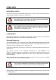
COMPLIANCE ELECTRICAL SAFETY This product conforms to the applicable requirements contained in the European Standard for electrical safety EN-60950 at the date of manufacture. This symbol refers to operations that must be performed by qualified personnel only. Example: opening the device. WARNING This symbol refers to operations where there is danger of electrical shock. Before opening the device make sure the power cable is disconnected to avoid electric shock.
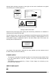
Warning labels indicating exposure to laser light and the device classification are applied onto the body of the scanner (Figure A): AVOID EXPOSURE LASER LIGHT IS EMITTED FROM THIS APERTURE CAUTION-CLASS 3B LASER LIGHT WHEN OPEN AVOID EXPOSURE TO BEAM DATALOGIC S.P.A. Via Candini, 2 40012 Calderara di Reno - Bologna - Italy Manufactured Volt Model No. Amp. Serial No. This product conforms to the applicable requirements of 21CFR1040 at the date of manufacture.
GENERAL VIEW DS8100A 8 7 1 6 2 3 4 5 Figure A – DS8100A viii 1 Laser Beam Output Window 5 Connector Panel 2 Laser Safety Label 6 Display 3 Product Label 7 Service Access Cap 4 Warning and Device Class Label 8 Mounting Holes
DS8100A 2 1 Figure B – DS8100A Oscillating Mirror Version 1 Laser Beam Output Window 2 Laser Safety Label 1 7 2 3 4 5 6 Figure C – Display and Keypad Panel 1 Programming Keypad 5 TX Data LED (Green) 2 Power On LED (Green) 6 Network LED (Red) 3 Phase On LED (Yellow) 7 LCD Display 4 Encoder LED (Yellow) ix
1 3 2 Figure D – Connector Panel for Standard Models 1 Lonworks 17-pin male connector 2 Lonworks 17-pin female connector 3 Serial interface and I/O 26-pin connector 1 4 2 3 Figure E – Connector Panel for Ethernet Models x 1 Lonworks 17-pin male connector 3 Serial interface and I/O 26-pin connector 2 Lonworks 17-pin female connector 4 Harting RJ industrial connector
GUIDE TO INSTALLATION POINT-TO-POINT INSTALLATION The following can be used as a checklist to verify all the necessary steps to complete installation of the DS8100A scanner. 1) Read all information in the section “Safety Regulations” at the beginning of this manual. 2) Correctly mount the scanner according to the information in par. 2.2 and position it at the correct reading distance as shown in par. 2.5 and par. 4.4.
MASTER/SLAVE LONWORKS INSTALLATION The following can be used as a checklist to verify all the steps necessary to complete installation of the DS8100A scanner in a Master/Slave Lonworks network. 1) Read all information in the section “Safety Regulations” at the beginning of this manual. 2) Correctly mount the scanner according to the information in par. 2.2 and position it at the correct reading distance as shown in par. 2.5 and par. 4.4.
7) Send the configuration to the Master. 8) Optionally, perform the ASR Network Configuration procedure for system backup purposes (see par. 5.2.1). 9) Exit the configuration program and run your application. The installation is now complete.
xiv
INTRODUCTION 1 1 INTRODUCTION 1.1 PRODUCT DESCRIPTION The DS8100A scanner is a barcode reader complete with decoder designed to provide an innovative and high performance solution in omnidirectional reading applications by combining the following advanced technologies with Datalogic solid experience in the material handling sector. Some of the main features of DS8100A are listed below: • scanning speed 1000 scans/sec. • reads all popular codes. • supply voltage from 20 to 30 Vdc.
DS8100A 1 Feature Benefit ACR™ • Advanced Code Reconstruction technology allows the reading of low aspect ratio labels placed anywhere on a parcel and enhances the readability of poorly printed or damaged codes. CD SQUARE™ • CD SQUARE™ provides useful information on label position and object shape elaborated during the barcode reading phase. This innovative technology identifies the area in which the code is located and measures the code distance from the scanner.
INTRODUCTION 1 1.3 MODEL DESCRIPTION The DS8100A scanner is available in versions that differ depending on the interface connection, the optical resolution and on the optic version: DS8100A - X X X X Laser Number: Optic Version: 0 = Linear 5 = Oscillating mirror 2 = Double laser 3 = Triple laser Communication Type: 0 = Standard version 1 = Ethernet version 1.3.
DS8100A 1 By limiting the raster width to the minimum necessary, the number of scans on the reading surface is increased. NOTE The oscillating mirror is completely controlled by software commands and therefore avoids complex mechanical calibrations. For details of the software configuration parameters see the Genius™ Help On Line. 1.4 INDICATORS The DS8100A has five LEDs on the rear panel. The indicators have the following functions: POWER ON (green) Indicates the scanner is turned on.
INTRODUCTION 1 1.
DS8100A 2 2 INSTALLATION To install the system follow the given procedure: 1. Select the mounting location for DS8100A; 2. Mount the DS8100A scanner; 3. Position the scanner with respect to the barcode; 4. Proceed with system electrical connection; 5. Install the Genius™ program on the PC and configure the scanner.
INSTALLATION 2 2.2 MECHANICAL MOUNTING 2.2.1 Mounting the Scanner 126.6 [4.98] DS8100A can be installed to operate in any position. There are 16 screw holes (M6 X 8) on the sides of the scanner for mounting. The diagram below can be used for installation; refer to par. 2.4 and par. 4.4 for correct positioning of the scanner with respect to the reading zone and scanner orientation. 46.7 [1.84] 172.5 [6.79] 45° 217 [8.54] 50 [1.97] 67.5 [2.66] M6 N°16 45° 67.5 [2.66] 46.8 [1.84] 50 [1.
DS8100A 192.3 [7.57] 2 46.7 [1.84] 254 [10.00] 45° mm inch 28° 50 [1.97] 67.5 [2.66] 46.8 [1.84] 45° 67.5 [2.66] 50 [1.97] 275.1 [10.83] Figure 5 - DS8100A Oscillating Mirror Model Overall Dimensions 2.2.2 Mounting the Scanner with Accessories The following accessories allow installing the DS8100A reader in the most suitable position for your network layout: - ST-163 mounting bracket; - FBK-8100 fast bracket.
INSTALLATION 2 The FBK-8100 is a fast bracket kit allowing quick and easy mounting of the scanner on the ST-163 bracket. It is particularly useful when performing a scanner automatic replacement (see par. 5.2), since the scanner can be simply substituted with a new one while maintaining its physical position within the network. First, it is necessary to fix the FBK-8100 round piece (2) to the ST-163 bracket (already mounted to the reading station frame) by means of the two screws (C).
DS8100A 2 2.3 ELECTRICAL CONNECTIONS All the connectors available for each scanner model are the following: Scanner Model Standard Ethernet Connectors 26-pin male serial interface and I/O connector 17-pin male Lonworks connector* 17-pin female Lonworks connector* 26-pin male serial interface and I/O connector 17-pin male Lonworks connector* 17-pin female Lonworks connector* RJ45 Industrial modular connector The table below gives the pinout of the C-BOX 100 terminal block connectors.
INSTALLATION 2.3.1 2 Main/Aux. Serial Interface and I/O Connector The DS8100A Standard and Fieldbus models are equipped with a 26-pin male D-sub connector for connection to the host computer, power supply and input/output signals.
DS8100A 2 Main Interface The main serial interface is compatible with the following electrical standards: RS232 RS485 full-duplex RS485 half-duplex (20 mA current loop) The 20 mA Current Loop interface is available by using the C-BOX 100 with the optional INT-30 accessory installed in it. The scanner communicates to the C-BOX 100 through the RS232 interface and the INT-30 converts the signals. The main serial interface type and its relative parameters (baud rate, data bits, etc.
INSTALLATION 2 RS485 Full-Duplex Interface The RS485 full-duplex interface is used for non-polled communication protocols in point-to-point connections over longer distances than those acceptable for RS232 communications or in electrically noisy environments. The overall maximum cable length should not exceed 1200 m (3937 ft).
DS8100A 2 Auxiliary Interface The auxiliary serial interface is equipped with RS232 full-duplex interface connections. The interface type is exclusive and is selectable through the Genius™ configuration program. The overall maximum cable length should not exceed 15 m (50 ft).
INSTALLATION 2 All inputs are optocoupled, polarity insensitive, and driven by a constant current generator; the command signal is filtered through an anti-disturbance circuit which generates a delay which can be set to 5 ms or 500 µs. In particular, EXT_TRIG/PS, IN3 and IN4 share the same value which usually corresponds to 5 ms when using a photoelectric sensor, while IN2/ENC has a different value which is set to 500 µs when this input is used for the Encoder.
DS8100A 2 Vext DS8100A EXTERNAL DEVICE V IN3A + 5V ~ + - ~ Ground Vext V IN4A + 5V ~ + - ~ INREF Ground Figure 18 - IN3/IN4 PNP Input Command using External Power DS8100A EXTERNAL DEVICE VS INREF + 5V ~ + V - ~ IN3A Ground EXTERNAL DEVICE + 5V ~ + V - ~ IN4A GND Ground Figure 19 - IN3/IN4 NPN Input Command using Scanner Power Input devices can be supplied by either scanner power (VS and GND) or external power supplies (Vext).
INSTALLATION 2 Outputs Three general purpose outputs are available.
DS8100A 2 The OUT3 electrical features are given below: Maximum voltage Collector current (pulse) Collector current (continuous) R on R off Off-state leakage current Maximum power dissipation ± 100 V 240 mA Max. 150 mA Max. 6 – 15 Ω > 500 Ω < 1 µA 550 mW at 50°C (Ambient temperature). DS8100A USER INTERFACE Vext 100 Vdc max A/B B/A Figure 21 – Output 3 Interface The command signal is filtered and generates a delay of about 50 µs for OUT1 and OUT2 and 1 ms for OUT3. 2.3.
INSTALLATION 2 Network Termination When building a Lonworks system the network must be properly terminated by positioning the BTK-8102 Lonworks terminator in the DS8100A master reader and the BTK-8100 Lonworks bus return in the last DS8100A slave reader.
DS8100A 2 Lonworks Interface The Lonworks network is used for both input and output connection to build a multi-sided or omni-station system connecting several readers. The DS8100A master usually employs the 17-pin female connector for output connection to the first slave, while the 17-pin male connector is terminated by inserting the BTK8102 terminator (see Figure 23 for details). Both connectors are always employed when connecting together the slave readers.
INSTALLATION 2 The following diagrams represent different network terminations using either the BTK-8102 Lonworks terminator or the BTK-8100 bus return. In Figure 27 the BTK-8102 terminator is indicated by the element, while the figure below shows its electrical circuit in details: Figure 26 – BTK-8102 Electrical Circuit The diagram below represents the termination of the double Lonworks line of a DS8100A working as master by means of the BTK-8102.
DS8100A 2 2.3.3 Ethernet Connector This connector is only available for DS8100A Ethernet models and allows the Ethernet connection between the host and the reader. Figure 29 – Harting RJ Industrial® Push Pull Male Connector 1 8 Figure 30 – DS8100A Harting RJ Industrial® Female Connector This interface and the connector pinout (see the following table) are IEEE 802.3 10 BaseT and IEEE 802.3u 100 Base Tx compliant. RJ45 Modular Jack Pinout Pin 1 2 3 6 4, 5, 7, 8 Name TX + TX RX + RX N.C.
INSTALLATION 2 Ethernet Interface The Ethernet interface (NIC) can be used for TCP/IP communication with a remote or local host computer by connecting the scanner to a LAN. It can also be connected directly to a host PC. The following is an example of a connection to a LAN through a Hub using a straight through cable: HUB / SWITCH DS8100A TX+ 1 1 TX- 2 2 RX+ 3 3 n. c. 4 4 n. c. 5 5 RX- 6 6 n. c. 7 7 n. c. 8 8 n. c.
DS8100A 2 Note that GND is internally connected to chassis. The cable shield is also connected to pin 1 - CHASSIS. DS8100A USER INTERFACE VS 9/13 23/25 GND 1 CHASSIS V+ (20 – 30 Vdc) V- (Ground) Chassis Earth Ground Figure 33 – Power Supply Using the 26-pin Connector 2.4 USER INTERFACE How To Build A Simple Interface Test Cable: The following wiring diagram shows a simple test cable including power, external (push-button) trigger and PC RS232 COM port connections.
INSTALLATION 2 The Pitch angle is represented by the value P in Figure 34. Position the reader in order to minimize the Pitch angle. P Figure 34 - "Pitch" angle The Skew angle is represented by the value S in Figure 35. S Figure 35 - "Skew" angle The Tilt angle is represented by the value T in Figure 36. For code reconstruction see par. 4.1.
2 DS8100A 2.6 TYPICAL LAYOUTS The DS8100A scanners can be connected in a variety of layouts depending on the number of scanners used and the required complexity of the reading station. These layouts range from Single Stand Alone to Complex Lonworks Networks. Several power supplies are available to power the reading stations. Photoelectric sensors used as code presence sensors and optical encoders to signal conveyor speed are also available accessories.
INSTALLATION 2.6.1 2 Point-to-Point Using a Point-to-Point layout, the data is transmitted on the Main interface as well as on the Auxiliary interface. The Main interface can be selected for RS232 or RS485 full-duplex communications. Two different layouts are available according to the DS8100A reader model used for the connection. Standard Models When On-Line operating mode is used, the reader is activated by an External Trigger (photoelectric sensor) when the object enters its reading zone.
DS8100A 2 2.6.2 Pass Through When Pass Through is activated on the Auxiliary interface, the DS8100A reader can be integrated in a network consisting of different scanners not provided with a Lonworks interface. This connection mode allows two or more devices to be connected to a single external serial interface. The DS8100A transmits the messages received by its auxiliary interface onto its main interface.
INSTALLATION 2 PLC Host P.S.* P.S.* Gryphon Fieldbus Network DS4600A DS4600A DS8100A CAB601X C-BOX 100 AUX C-BOX 100 C-BOX 100 P.S.* 2 1 2 1 PWR-120 1 * Main Serial Interface 2 Auxiliary Serial Interface P.S. (Presence Sensor) connected to External Trigger/PS input. Figure 40 – Pass Through Connection for Fieldbus Models 2.6.
DS8100A 2 DS8100A - Master C-BOX 100 CAB601X MAIN DS4600A Slave 1 1 AUX P.S.* 2 Local Host 2 1 C-BOX 100 DS4600A Slave 2 PWR-120 C-BOX 100 1 1 * Main Serial Interface 2 Auxiliary Serial Interface P.S. (Presence Sensor) connected to External Trigger/PS input. Figure 41 – RS232 Master/Slave for DS8100A Standard Models Remote PLC DS8100A Master Fieldbus Network CAB601X AUX C-BOX 100 DS4600A Slave 2 P.S.* 2 1 C-BOX 100 DS4600A Slave 1 PWR-120 C-BOX 100 * P.S.
INSTALLATION 2.6.4 2 Multiplexer The Multiplexer connection is used to integrate a DS8100A slave reader in a Multidrop network consisting of different scanners not provided with a Lonworks interface. Each scanner is connected half-duplex main interface. P.S.* to a Multiplexer (MX4000) with the RS485 P.S.* P.S.* DS8100A DS4600A C-BOX 100 C-BOX 100 #31 #1 DS4600A PWR-120 C-BOX 100 MX4000 1 #0 Local Host 1 * RS485 HD Main Interface P.S.
DS8100A 2 2.6.5 Local Lonworks Network A local Lonworks network allows logically connecting a DS8100A master reader with up to 31 DS8100A slaves. Actually, the maximum number of readers to be employed in the network depends on the system operating conditions, that is adopted operating mode and amount of data stream.
INSTALLATION 2 Small Synchronized Network When building a small local Lonworks network (less than 10 scanners), the DS8100A master reader must be connected to a local host computer or a C-BOX 100 by means of a cable connected to the 26-pin D-sub male connector. The master reader connects to the first slave reader of the system through the local Lonworks 17-pin female connector.
DS8100A 2 The following image shows a system consisting of five readers where the external signals (trigger, encoder, serial to host, etc.) are connected to the master through the C-BOX 100. The system is powered by the PWR-240 where: • the master is connected through CAB-860X, which also provides bus termination • the last slave is connected through CAB-830X, which also provides bus return.
INSTALLATION 2 Large Synchronized Network When building a large local Lonworks network (more than 10 scanners), an SC6000 Controller must be used together with a PWO power supply/junction box unit. In this case the SC6000 unit acts as the system master and is connected to the host through one of its interfaces. All scanners act as slaves and are connected to the SC6000 through the PWO power supply/junction box.
DS8100A 2 SC6000 Conveyor Figure 47 – Large Synchronized Network Reading Station 36
INSTALLATION 2 Redundant System For large local Lonworks networks, a redundant system can per configured in which two SC6000 Controllers are used together with their respective PWO power supply/junction box units. The scanners are distributed equally between the PWO units. In this case one of the SC6000 Controllers is dedicated as the working or active unit while the other functions as a dedicated protecting or backup unit.
DS8100A 2 Multidata Network In this layout, one master and up to 7 DS8100A slave readers have their own P.S. and therefore multiple reading phases. Each P.S. is connected through a C-BOX 100, which in turn is connected to its relative scanner through a CAB-601X cable. The master sends all the individual messages collected from the Lonworks interface as well as its own to the Local Host through its C-BOX 100.
INSTALLATION 2.6.6 2 Fieldbus Network The Fieldbus (Ethernet) model offers connectivity without any converter or adapter needed. The DS8100A master Fieldbus communicates with a remote host (for ex. remote PC connected via Internet) by means of a cable connected to the Fieldbus (Ethernet) connector provided. It can be activated by a signal generated by the remote Host or by a physical presence sensor. The external signals (trigger, encoder) are connected to the master through the C-BOX 100.
DS8100A 2 2.
SOFTWARE CONFIGURATION 3 3 SOFTWARE CONFIGURATION 3.1 GENIUS™ INSTALLATION Genius™ is a new Datalogic scanner configuration tool providing several important advantages: • Wizard approach for low skilled users; • Multi-language version; • Defined configuration directly stored in the reader; • Communication protocol independent from the physical interface allowing to consider the reader as a remote object to be configured and monitored.
DS8100A 3 After defining the parameter values the following window appears allowing to complete the reader configuration as follows: - Saving the configuration to disk; - Switching to Advanced mode; - Sending the configuration to the scanner. Figure 52 - Genius™ Wizard Closing Window Test Operating Mode This operating mode is not available when DS8100A works as slave.
SOFTWARE CONFIGURATION 3 On Line Operating Mode Figure 54 - On Line Mode Selection This operating mode causes the reader to be connected to an external Presence Sensor using EXT TRIG/PS A and EXT TRIG/PS B inputs. During the active phase of the presence sensor, the DS8100A reader tries to acquire and correctly decode the code. In case the decoding phase is successful, the barcode characters are transmitted on the serial interface. Otherwise, a no read message is sent.
DS8100A 3 3.2.2 Genius™ Network Setup Through Master The Network Setup allows configuring your Local Lonworks Network through the Master using Genius™. Three different procedures are available to define the number of network slave scanners, their label and address according to two main conditions: Condition Available Procedure Feature Unknown Slave Addresses Net-Autoset automatically assigns random addresses to slave or Stand Alone scanners.
SOFTWARE CONFIGURATION 3 The following dialog box appears asking whether to send the configuration to the Master or not: icon available on the Toolbar to make the 2. Click the "Yes" button, then click on the “Devices” area appear next to the Parameter Explorer window. By repeatedly clicking the icon this area will be displayed or hidden.
DS8100A 3 3. Then, proceed with the network setup by using one of the icons available on the Tool Bar according to the procedure to follow: = Net-Autoset procedure = Network Wizard procedure = Express Network Setup procedure Net-Autoset This procedure is to be used when all scanner addresses and labels are unknown (typically when configuring the network for the first time or whenever a network reconfiguration is required).
SOFTWARE CONFIGURATION 3 Network Wizard Before performing this procedure, a Lonworks address must be assigned to each slave scanner. The most practical method is through the Net-Autoset procedure. See par. 3.2.3 for alternative address assignment methods. Once all addresses have been assigned, the Network Wizard is to be used when one or more scanner addresses and labels need to be modified. 1. Click on the button to open the Network Wizard dialog box: a.
DS8100A 3 2. If desired, select a slave scanner within the "Current Devices" area and click on the icon (or select the "Show Device" option from the right-click menu) to make the dialog box appear as follows: • • The "Show Device" option is particularly useful after the Net-Autoset procedure or whenever it is necessary to know which address is assigned to a specific slave scanner.
SOFTWARE CONFIGURATION 3.2.3 3 Alternative Slave Address Assignment As alternatives to Network Setup through the Master, each Slave scanner can be assigned an address through the following methods: • address setting through the Local Device Network Settings item in the Device Menu with the slave scanner connected to Genius™ • manual address setting through slave scanner keyboard (see par. 2.7.1 for details) 3.
DS8100A 3 3.4 PARAMETER DEFAULT VALUES The following table contains the list of the factory default settings for the DS8100A. Genius™ also allows checking the parameter default values by selecting the "Compare parameters" option available in the Tools menu and comparing the current scanner configuration to the default one.
SOFTWARE CONFIGURATION Parameter Reading Parameters Overflow Stop Ratio Reading Mode Reading Condition Reconstruction Parameters Enabled Stacked Code Extended Min Match Position Tolerance Duration Tolerance Min Start/Stop Number Inter Char Gap Addon Overflow Ration Scan Line Amplitude Amplitude Settings Enable PackTrack Calibration Direction PS Offset Data Communication Settings Host Application Protocol Type Data Format Header TX Start Termination After No Read Message Message Tx Trigger Selection Format
DS8100A 3 Parameter Auxiliary Serial Port Data Tx Heartbeat Pass Through Parameters Baud Rate Parity Data Bits Stop Bits Digital I/O Setting Digital Input Lines Setting Debouncing For Input 1, 3 and 4 Debouncing For Input 2 Input 1 Active Level Overridden by Op. Mode Input 2 Active Level Overridden by Op. Mode Input 3 Active Level Overridden by Op. Mode Input 4 Active Level Overridden by Op.
READING FEATURES 4 4 READING FEATURES 4.1 ADVANCED CODE RECONSTRUCTION (ACR™ 4) The traditional way of barcode reading could be called “Linear Reading”. In this case, the laser beam crosses the barcode symbol from its beginning to its end as shown in the following figure: Laser Beam Figure 59 – Linear Reading In Advanced Code Reconstruction mode it is no longer necessary for the laser beam to cross the label from the start to the end.
DS8100A 4 The decoder will be able to read the label + α max and - α max as shown in the following figure: with a tilt angle between 0° OK OK No Read No Read No Read Conveyor -α +α OK OK OK Laser Beam Figure 62 – Reading Zones with α Max The formulas to calculate α maximum depend on various parameters such as: label height, number of scans per second, code motion speed, etc. Minimum label heights at different conveyor speeds are given in the tables in par. 4.3.
READING FEATURES 4 All PackTrack™ functionalities are programmed via the Genius™ tool (refer to the Genius™ Help On-Line for details). For correct functioning, the PackTrack™ operating mode requires a calibration just after the installation of the scanners. This operation is absolutely necessary to make the scanner recognize its position in space. Thus, a fixed reference system is required.
DS8100A 4 4.2.1 PackTrack™ Calibration for DS8100A By means of the Genius™ software tool SPY, the user can perform PackTrack™ calibration. Select the “SPY” option from the Tools menu or click on the related icon on the Genius™ toolbar to open the following dialog box: Note: When selecting a slave scanner through the Master, click on the slave to calibrate in the Devices window, then click the SPY icon.
READING FEATURES 4 By selecting the “PackTrack Calibration” option a further dialog box appears allowing to start calibration: Position 1 Position 2 Position 3 Figure 67 – Performing the PackTrack™ Calibration 1. Place the code at the desired position on the scan line (i.e. Position 1) 2. Measure the X, Y and Z coordinates relative to the center of the code and enter them into the corresponding edit boxes. 3. Press the Calibrate button for Position 1 to start the calibration. 4.
DS8100A 4 4.2.2 PackTrack™ Calibration for DS8100A Oscillating Mirror Models The DS8100A oscillating mirror models can be used in PackTrack™ operating mode only when the scanner is mounted so that the scan line is parallel to the conveyor direction as shown in the following figure: Conveyor Direction Scan Line Figure 68 – Oscillating Mirror Models in PackTrack™ Mode PackTrack™ Calibration must be made while the scanning plane is perpendicular to the conveyor plane and fixed (not oscillating). 4.
READING FEATURES Conveyor Speed (m/s) 0.25 0.30 Code 39 0.33 Code Resolution 0.38 (mm) 0.50 0.72 1.00 4 0.5 9 10 11 12 15 20 27 Minimum Code Height for ACR Reading (mm) 45° 30° 1 1.5 2 2.5 3 0.5 1 1.5 2 2.5 9 11 12 14 15 6 7 8 9 10 11 12 13 15 16 7 7 8 10 11 11 12 14 15 17 7 8 9 10 11 13 13 15 16 18 8 8 9 10 12 16 16 17 18 20 9 10 11 12 13 21 22 22 23 24 13 13 14 14 15 28 29 29 30 31 17 17 18 18 19 3 11 12 12 13 14 16 20 Ratio 3:1; Interdigit = Module Size Table 2 Conveyor Speed (m/s) 0.25 0.
DS8100A 4 4.4 READING DIAGRAMS DS8100A-2X10 (0.50 mm/20 mils) The diagram shows an average reading area obtained considering different barcode types of variable quality. 28 70 24 60 20 50 16 40 12 30 8 20 4 10 0 0 -4 -10 -8 -20 -12 -30 -16 -40 -20 -50 -24 -60 0 24 32 40 48 56 64 68 0 60 80 100 120 140 160 180 -28 -700 (in) (cm) Note: (0,0) is the center of the laser beam output window.
READING FEATURES 4 DS8100A-2X10 (0.38 mm/15 mils) The diagram shows an average reading area obtained considering different barcode types of variable quality. 28 70 24 60 20 50 16 40 12 30 8 20 4 10 0 0 -4 -10 -8 -20 -12 -30 -16 -40 -20 -50 -24 -60 0 24 32 40 48 56 64 68 0 60 80 100 120 140 160 180 (in) (cm) -28 -700 (in) (cm) Note: (0,0) is the center of the laser beam output window. CONDITIONS Code = Interleaved 2/5 or Code 39 PCS = 0.
DS8100A 4 DS8100A-3X00 (0.50 mm/20 mils) The diagram shows an average reading area obtained considering different barcode types of variable quality. 28 70 24 60 20 50 16 40 12 30 8 20 4 10 0 0 -4 -10 -8 -20 -12 -30 -16 -40 -20 -50 -24 -60 0 24 32 40 48 56 64 68 0 60 80 100 120 140 160 180 -28 -700 (in) (cm) Note: (0,0) is the center of the laser beam output window.
READING FEATURES 4 DS8100A-3X10 (0.38 mm/15 mils) The diagram shows an average reading area obtained considering different barcode types of variable quality. 28 70 24 60 20 50 16 40 12 30 8 20 4 10 0 0 -4 -10 -8 -20 -12 -30 -16 -40 -20 -50 -24 -60 0 16 24 32 40 48 56 64 (in) 0 40 60 80 100 120 140 160 (cm) -70 -28 (cm) (in) Note: (0,0) is the center of the laser beam output window. CONDITIONS Code = Interleaved 2/5 or Code 39 PCS = 0.
DS8100A 4 DS8100A-3X20 (0.30 mm/12 mils) The diagram shows an average reading area obtained considering different barcode types of variable quality. 24 60 20 50 16 40 12 30 8 20 4 10 0 0 -4 -10 -8 -20 -12 -30 -16 -40 -20 -50 0 24 32 40 48 56 64 0 60 80 100 120 140 160 -60 -24 (in) (cm) Note: (0,0) is the center of the laser beam output window. CONDITIONS Code = Interleaved 2/5 or Code 39 PCS = 0.
READING FEATURES 4 DS8100A-3X30 (0.25 mm/10 mils) The diagram shows an average reading area obtained considering different barcode types of variable quality. 20 50 16 40 12 30 8 20 4 10 0 0 -4 -10 -8 -20 -12 -30 -16 -40 0 16 24 32 40 48 0 40 60 80 100 120 (in) (cm) -50 -20 (in) (cm) Note: (0,0) is the center of the laser beam output window. CONDITIONS Code = Interleaved 2/5 or Code 39 PCS = 0.
DS8100A 4 DS8100A-3X05 (0.50 mm/20 mils) The diagram shows an average reading area obtained considering different barcode types of variable quality. 28 70 24 60 20 50 16 40 12 30 8 20 4 10 0 0 -4 -10 -8 -20 -12 -30 -16 -40 -20 -50 -24 -60 0 24 32 40 48 56 64 68 0 60 80 100 120 140 160 180 -28 -700 (in) (cm) Note: (0,0) is the center of the laser beam output window.
READING FEATURES 4 DS8100A-3X15 (0.38 mm/15 mils) The diagram shows an average reading area obtained considering different barcode types of variable quality. 28 70 24 60 20 50 16 40 12 30 8 20 4 10 0 0 -4 -10 -8 -20 -12 -30 -16 -40 -20 -50 -24 -60 0 16 24 32 40 48 56 64 (in) 0 40 60 80 100 120 140 160 (cm) -70 -28 (cm) (in) Note: (0,0) is the center of the laser beam output window. CONDITIONS Code = Interleaved 2/5 or Code 39 PCS = 0.
DS8100A 4 DS8100A-3X25 (0.30 mm/12 mils) The diagram shows an average reading area obtained considering different barcode types of variable quality. 24 60 20 50 16 40 12 30 8 20 4 10 0 0 -4 -10 -8 -20 -12 -30 -16 -40 -20 -50 0 16 24 32 40 48 56 0 40 60 80 100 120 140 -60 -24 (in) (cm) Note: (0,0) is the center of the laser beam output window. CONDITIONS Code = Interleaved 2/5 or Code 39 PCS = 0.
READING FEATURES 4 DS8100A-3X35 (0.25 mm/10 mils) The diagram shows an average reading area obtained considering different barcode types of variable quality. 20 50 16 40 12 30 8 20 4 10 0 0 -4 -10 -8 -20 -12 -30 -16 -40 0 16 24 32 40 48 0 40 60 80 100 120 (in) (cm) -50 -20 (in) (cm) Note: (0,0) is the center of the laser beam output window. CONDITIONS Code = Interleaved 2/5 or Code 39 PCS = 0.
DS8100A 5 5 MAINTENANCE 5.1 CLEANING Clean the laser beam output window periodically for correct operation of the scanner (see Figure A and Figure B in chapter "General View"). Dust, dirt, etc. on the window may alter the reading performance. Repeat the operation frequently in particularly dirty environments. Use soft material and alcohol to clean the window and avoid any abrasive substances. Clean the window of the DS8100A when the scanner is turned off or at least when the laser beam is not active.
MAINTENANCE 5.2.2 5 Scanner Replacement Procedure The ASR procedure requires replacing one scanner at a time. NOTE Slave 1. Power down the entire system. 2. Replace the Slave scanner with a new one (default settings). 3. Power up the system and wait for initialization. Master 1. Load the saved configuration from file (.ddc) to the new Master. 2. Power down the entire system. 3. Replace the Master scanner with the new one. 4. Power up the system and wait for initialization.
DS8100A 6 6 TROUBLESHOOTING NOTE Before contacting your local Datalogic office or Datalogic Partner or ARC, it is suggested to save the device configuration to a *.ddc file by means of the Genius™ software configuration program and check the device exact model and serial number. TROUBLESHOOTING GUIDE Problem Power On: the “Power On” LED is not lit. On Line Mode: the Master’s “Phase On” LED is not lit (when external trigger activates).
TROUBLESHOOTING 6 TROUBLESHOOTING GUIDE Problem On Line Mode and Serial On Line Mode: the reader does not respond correctly to the expected external signal end. Reading: it is not possible to read the target barcode (always returns No Read) Suggestion In the Genius™ software configuration program select the OPERATING MODES folder and check the “Reading Phase Timeout” parameterization. • • • • • • • Communication: the device is not transmitting anything to • the host.
DS8100A 6 TROUBLESHOOTING GUIDE Problem Communication: the scanner “Network” LED is not lit. Suggestion • If the LED is OFF, check the connections between the DS8100A slaves and the SC6000 or DS8100A master. If the error persists, contact your Datalogic distributor. How do I obtain my units’ serial • The device serial number is printed on a label that is affixed above the connector panel of numbers? the reader. • The serial number is also displayed when connecting the device through the Genius™ program.
TECHNICAL FEATURES 7 7 TECHNICAL FEATURES ELECTRICAL FEATURES Supply voltage Power consumption Common Communication Interfaces 20 to 30 Vdc 20 W typical 30 W Max. (including startup current) Main Baud Rate RS232 RS485 full-duplex RS485 half-duplex 20 mA C.L. 1200 to 115200 19200 (INT-30 with C-BOX 100 only) Auxiliary RS232 1200 to 115200 Other Lonworks Model–Dependent Communication Ethernet Interfaces Inputs Ext. Trigger 1, 3 aux.
DS8100A 7 SOFTWARE FEATURES Readable Codes Code selection Headers and Terminators Operating modes Configuration modes Parameter storage ENVIRONMENTAL FEATURES Operating temperature Storage temperature Humidity Ambient light immunity Vibration resistance IEC 68-2-6 test FC 2 hours on each axis Shock resistance: IEC 68-2-27 test EA 3 shocks on each axis Interleaved 2/5 Code 39 Standard Codabar Code 128 EAN 128 Code 93 (standard and full ASCII) EAN/UPC (including Add-on 2 and Add-on 5) Up to 10 codes during
GLOSSARY ACR™ 4 Each version of the base has the powerful code reconstruction technology (ACR™ 4). The new fourth generation ACR™ considerably increases the code reconstruction reading capability in the case of damaged or very tilted barcodes. Aperture Term used on the required CDRH warning labels to describe the laser exit window. Barcode A pattern of variable-width bars and spaces which represents numeric or alphanumeric data in machine-readable form.
Host A computer that serves other terminals in a network, providing services such as network control, database access, special programs, supervisory programs, or programming languages. Interface A shared boundary defined by common physical interconnection characteristics, signal characteristics and meanings of interchanged signals. LED (Light Emitting Diode) A low power electronic device that can serve as a visible or near infrared light source when voltage is applied continuously or in pulses.
Scanner A device that examines a printed pattern (barcode) and either passes the uninterpreted data to a decoder or decodes the data and passes it onto the Host system. Serial Port An I/O port used to connect a scanner to your computer. Signal An impulse or fluctuating electrical quantity (i.e.: a voltage or current) the variations of which represent changes in information. Skew Rotation about the Y-axis.
INDEX A L Accessories; 5 ACR™ 4; 53 LEDs; 4 C Cleaning; 70 Compliance; vi Electrical Safety; vi Laser Safety; vi Power Supply; vii Standard Regulations; vi WEEE Compliance; vii Connectors 26-pin connector; 11 Ethernet; 22 D Default Values; 50 E Electrical Connections; 10 G Genius™ Advanced Configuration; 49 Installation; 41 Wizard for Quick Reader Setup; 41 Glossary; 77 Guide to Installation; xi I Indicators; 4 Inputs; 14 Installation; 6 Mounting the Scanner; 7 Mounting with Accessories; 8 Interfaces Au
DATALOGIC S.p.A.