DS6500 INSTALLATION QUICK REFERENCE
CONTENTS DS6500-100-010 MASTER/SLAVE MODEL ...........................................................................................................1 DS6500-100-011 PROFIBUS MODEL.....................................................................................................................8 DS6500-100-012 ETHERNET MODEL ..................................................................................................................13 DS6500-100-015 DEVICENET MODEL...................................
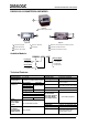
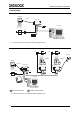
DS6500 MASTER/SLAVE MODEL DS6500-100-010 MASTER/SLAVE MODEL 1 Figure A 1 Laser Beam Output Window 1 5 1 3 4 3 2 2 Figure B Figure C 1 Programming Keypad 4 Power On LED (Red) 1 Main/Aux.
DS6500 MASTER/SLAVE MODEL SOFTWARE FEATURES Readable Codes Interleaved 2/5 Code 39 standard Codabar Code 128 EAN 128 Code 93 (Standard & Full ASCII) EAN/UPC (including Add-on 2 And Add-on 5) Code Selection Up to 10 codes during one reading phase Headers and Up to 128-byte headers and 128-byte terminators Terminators Operating Modes On Line, Automatic, Test, PackTrack™ Config.
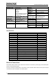
DS6500 MASTER/SLAVE MODEL The details of the connector pins are indicated in the following table: 25-pin D-Sub Connector Pinout Pin Name Function Chassis - internally connected to GND 1 CHASSIS Cable shield connected to chassis 20 RXAUX Receive data of auxiliary RS232 (referred to GND) 21 TXAUX Transmit data of auxiliary RS232 (referred to GND) 8 OUT 1+ Configurable digital output 1 – positive pin 22 OUT 1Configurable digital output 1 – negative pin 11 OUT 2+ Configurable digital output 2 – positive pin
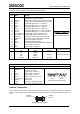
DS6500 MASTER/SLAVE MODEL Connectivity: Point-to-Point Layout DS6500 CAB-600X C-BOX 100 Local Host *P.S. PG6000 * P.S. (Presence Sensor) connected to External Trigger/PS input. Pass Through Layout *P.S. *P.S. Gryphon DS4600A DS4600A < T EN T < < EN < DS6500 CAB-600X C-BOX 100 C-BOX 100 C-BOX 100 AUX MAIN *P.S. 2 1 2 Local Host 1 PWR-120 1 Main Serial Interface * 4 2 Auxiliary Serial Interface P.S. (Presence Sensor) connected to External Trigger/PS input.
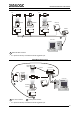
DS6500 MASTER/SLAVE MODEL Multiplexer Layout *P.S. *P.S. < DS4600A DS4600A PWR-120 EN T < DS6500 < < EN T CAB-600X C-BOX 100 C-BOX 100 #31 C-BOX 100 MX4000 #0 #1 1 Local Host 1 RS485 HD Main Interface * P.S. (Presence Sensor) connected to External Trigger/PS input. RS232 Master/Slave Layout DS6500 Master CAB-600X C-BOX 100 EN 2 < < T DS4600A Slave 1 1 *P.S.
DS6500 MASTER/SLAVE MODEL Local Lonworks Network CAB-60XX CAB-610X BTK-6000 C-BOX 100** Master Encoder*** BTK-6000 Slave 1 *P.S. Local Host CAB-63XX PWR-120 Small Synchronized Network with 2 Readers * P.S. (Presence Sensor) connected to External Trigger/PS input. ** C-BOX 100 modified to accept scanner power. *** Encoder connected to IN2/ENC input. Local Lonworks Network Slave 2 Slave 1 Master C-BOX 100** BTK-6000 CAB-610X CAB-610X CAB-600X *P.S.
DS6500 MASTER/SLAVE MODEL Large Synchronized Network ** * * P.S. (Presence Sensor) connected to External Trigger/PS input. ** Encoder connected to IN2/ENC input. Large Synchronized Network with DX6X00 and DS6XXX Scanners .
DS6500 PROFIBUS MODEL DS6500-100-011 PROFIBUS MODEL 1 Figure A 1 Laser Beam Output Window 3 5 1 4 3 2 1 2 Figure B Figure C 1 Programming Keypad 4 Power On LED (Red) 1 Profibus 9-pin Female Connector (white) 2 TX Data LED (Green) 5 LCD Display 2 Lonworks 9-pin Female Connector 3 Phase On LED (Yellow) 3 Main/Aux.
DS6500 PROFIBUS MODEL SOFTWARE FEATURES Readable Codes Interleaved 2/5 Code 39 standard Codabar Code 128 EAN 128 Code 93 (Standard & Full ASCII) EAN/UPC (including Add-on 2 And Add-on 5) Code Selection Up to 10 codes during one reading phase Headers and Up to 128-byte headers and 128-byte terminators Terminators Operating Modes On Line, Automatic, Test, PackTrack™ Config.
DS6500 PROFIBUS MODEL 26-pin D-Sub Connector Pinout Pin Name Function Chassis - internally connected to GND Cable shield connected to chassis 20 RXAUX Receive data of auxiliary RS232 (referred to GND) 21 TXAUX Transmit data of auxiliary RS232 (referred to GND) 8 OUT 1+ Configurable digital output 1 – positive pin 22 OUT 1Configurable digital output 1 – negative pin 11 OUT 2+ Configurable digital output 2 – positive pin 12 OUT 2Configurable digital output 2 – negative pin 9 1 16 OUT 3A Configurable digita
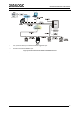
DS6500 PROFIBUS MODEL Connectivity: Point-to-Point Layout Remote Host Fieldbus Network DS6500 CAB-601X C-BOX 100 *P.S. PG6000 * P.S. (Presence Sensor) connected to External Trigger/PS input. Pass Through Layout Remote Host *P.S. *P.S. Gryphon DS4600A < < DS6500 < < EN T CAB-601X C-BOX 100 AUX DS4600A EN T Fieldbus Network C-BOX 100 C-BOX 100 *P.S. 2 1 2 1 PWR-120 1 Main Serial Interface * 2 Auxiliary Serial Interface P.S.
DS6500 PROFIBUS MODEL Local Lonworks Network Remote Host Fieldbus Network Slave 2*** Master Slave 1*** C-BOX 100** CAB-610X CAB-610X CAB-60XX P.S.* CAB-610X Encoder**** CAB-610X CAB-610X CAB-63XX BTK-6000 Slave 5*** Slave 3*** Slave 4*** PWR-240 CAB-63XX Fieldbus Small Synchronized Network * P.S. (Presence Sensor) connected to External Trigger/PS input. ** C-BOX 100 modified to accept scanner power.
DS6500 ETHERNET MODEL DS6500-100-012 ETHERNET MODEL 1 Figure A 1 Laser Beam Output Window 3 5 1 3 4 1 2 2 Figure B Figure C 1 Programming Keypad 4 Power On LED (Red) 1 RJ45 Modular Connector for Ethernet Interface 2 TX Data LED (Green) 5 LCD Display 2 Lonworks 9-pin Female Connector 3 Phase On LED (Yellow) 3 Main/Aux.
DS6500 ETHERNET MODEL SOFTWARE FEATURES Readable Codes Interleaved 2/5 Code 39 standard Codabar Code 128 EAN 128 Code 93 (Standard & Full ASCII) EAN/UPC (including Add-on 2 And Add-on 5) Code Selection Up to 10 codes during one reading phase Headers and Up to 128-byte headers and 128-byte terminators Terminators Operating Modes On Line, Automatic, Test, PackTrack™ Config.
DS6500 ETHERNET MODEL 26-pin D-Sub Connector Pinout Pin Name Function Chassis - internally connected to GND Cable shield connected to chassis 20 RXAUX Receive data of auxiliary RS232 (referred to GND) 21 TXAUX Transmit data of auxiliary RS232 (referred to GND) 8 OUT 1+ Configurable digital output 1 – positive pin 22 OUT 1Configurable digital output 1 – negative pin 11 OUT 2+ Configurable digital output 2 – positive pin 12 OUT 2Configurable digital output 2 – negative pin 9 1 16 OUT 3A Configurable digita
DS6500 ETHERNET MODEL Connectivity: Point-to-Point Layout Remote Host Fieldbus Network DS6500 C-BOX 100 CAB-601X *P.S. PG6000 * P.S. (Presence Sensor) connected to External Trigger/PS input. Pass Through Layout Remote Host *P.S. *P.S. Gryphon DS4600A < < < EN T DS6500 CAB-601X C-BOX 100 AUX C-BOX 100 C-BOX 100 *P.S. 2 1 PWR-120 1 Main Serial Interface * 16 2 Auxiliary Serial Interface P.S. (Presence Sensor) connected to External Trigger/PS input.
DS6500 ETHERNET MODEL Local Lonworks Network Remote Host Fieldbus Network Slave 2*** Master Slave 1*** C-BOX 100** CAB-610X CAB-610X CAB-60XX P.S.* CAB-610X Encoder**** CAB-610X CAB-610X CAB-63XX BTK-6000 Slave 5*** Slave 3*** Slave 4*** PWR-240 CAB-63XX Fieldbus Small Synchronized Network * P.S. (Presence Sensor) connected to External Trigger/PS input. ** C-BOX 100 modified to accept scanner power.
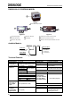
DS6500 DEVICENET MODEL DS6500-100-015 DEVICENET MODEL 1 Figure A 1 Laser Beam Output Window 1 5 1 3 4 3 2 2 Figure C Figure B 1 Programming Keypad 4 Power On LED (Red) 1 Main/Aux.
DS6500 DEVICENET MODEL SOFTWARE FEATURES Readable Codes Interleaved 2/5 Code 39 standard Codabar Code 128 EAN 128 Code 93 (Standard & Full ASCII) EAN/UPC (including Add-on 2 And Add-on 5) Code Selection Up to 10 codes during one reading phase Headers and Up to 128-byte headers and 128-byte terminators Terminators Operating Modes On Line, Automatic, Test, PackTrack™ Config.
DS6500 DEVICENET MODEL The details of the connector pins are indicated in the following table: 26-pin D-Sub Connector Pinout Pin Name Function Chassis - internally connected to GND Cable shield connected to chassis 20 RXAUX Receive data of auxiliary RS232 (referred to GND) 21 TXAUX Transmit data of auxiliary RS232 (referred to GND) 8 OUT 1+ Configurable digital output 1 – positive pin 22 OUT 1Configurable digital output 1 – negative pin 11 OUT 2+ Configurable digital output 2 – positive pin 12 OUT 2Confi
DS6500 DEVICENET MODEL Connectivity: Point-to-Point Layout Remote Host Fieldbus Network DS6500 C-BOX 100 CAB-601X *P.S. PG6000 * P.S. (Presence Sensor) connected to External Trigger/PS input. Pass Through Layout Remote Host *P.S. *P.S. Gryphon DS4600A < < DS6500 < < EN T CAB 601X C-BOX 100 AUX DS4600A EN T Fieldbus Network C-BOX 100 C-BOX 100 *P.S. 2 1 2 1 PWR-120 1 Main Serial Interface * 2 Auxiliary Serial Interface P.S.
DS6500 DEVICENET MODEL Local Lonworks Network Remote Host Fieldbus Network Slave 2*** Master Slave 1*** C-BOX 100** CAB-610X CAB-610X CAB-60XX P.S.* CAB-610X Encoder**** CAB-610X CAB-610X CAB-63XX BTK-6000 Slave 5*** Slave 3*** Slave 4*** PWR-240 CAB-63XX Fieldbus Small Synchronized Network * P.S. (Presence Sensor) connected to External Trigger/PS input. ** C-BOX 100 modified to accept scanner power.
DS6500 OSCILLATING MIRROR MODEL DS6500-105-0XX OSCILLATING MIRROR MODEL 1 Figure A 1 Laser Beam Output Window Oscillating mirror models are used when coverage of a large reading area is required, mainly in picket fence applications. The DS6500 scanner mounts a dedicated optic head with integrated oscillating mirror driven by a linear motor. The speed, precision, repeatability, and reliability of this driving technology assure high level performance.
DS6500 OSCILLATING MIRROR MODEL In the above case, the zone where the scan line is perpendicular to the reflecting surface corresponds to a neutral zone at the center of the reading field. The mirror can be deflected up to 40°. Oscillation with respect to the output window median axis is asymmetrical (see figure below). ° 37.5 40° -2.
COMMON FEATURES COMMON FEATURES C-BOX 100 Pinout for DS6500: The table below gives the pinout of the C-BOX 100 terminal block connectors.
COMMON FEATURES Mechanical Installation: The DS6500 reader can be positioned and installed in the best way possible as a result of the Step-A-HeadTM feature. Thanks to the separation between Head and Base, you can modify the orientation of the decoder base, and therefore display-keypad and connector panels, while keeping the optic head in the correct reading position.
COMMON FEATURES Typical Installations: Standard Installation The DS6500 scanner is mounted on the ST-237 106° mounting bracket which guarantees a built-in Skew angle (S in the figure below) of 16° with respect to the frame plane (typically the Skew angle should be between 10° - 20°). This avoids the direct reflection of the laser light emitted by the scanner.
COMMON FEATURES Conveyor Speed (m/s) 2/5 Interleaved Code Resolution (mm) 0.25 0.30 0.33 0.38 0.50 0.72 1.00 0.5 10 12 13 14 18 24 33 1 12 14 14 16 19 25 34 Minimum Code Height for ACR Reading (mm) 45° 30° 1.5 2 2.5 3 0.5 1 1.5 2 14 16 18 20 7 9 10 12 15 17 19 21 8 9 11 12 16 18 20 22 8 10 11 13 18 19 21 23 9 11 12 14 21 23 25 26 11 12 14 15 27 28 30 32 15 16 17 19 35 36 38 40 20 21 22 23 2.5 13 14 14 15 17 20 25 3 15 15 16 17 18 22 26 2.5 12 12 13 13 14 17 20 3 13 14 14 15 16 18 21 2.
COMMON FEATURES Reading Diagrams: In the following reading diagrams (0,0) is the center of the laser beam output window. DS6500-100-0XX CONDITIONS Code = Interleaved 2/5 or Code 39 PCS = 0.90 Pitch angle = 0° Skew angle = 10° - 20° Tilt angle = 0° 20 50 16 40 12 30 8 20 4 10 0 0 -4 -10 -8 -20 -12 -30 -16 -40 -20 -50 0 4 8 12 16 0 10 20 30 40 20 50 24 60 28 32 36 40 70 80 90 100 (in) (cm) 0.375 mm (15 mils) 0.3 mm (12 mils) 0.
COMMON FEATURES Reading Diagrams: DS6500-200-0XX 0 0 CONDITIONS Code = Interleaved 2/5 or Code 39 PCS = 0.90 Pitch angle = 0° Skew angle = 10° - 20° Tilt angle = 0° 30 75 24 60 18 45 12 30 6 15 0 0 -6 -15 -12 -30 14 35 20 50 26 32 38 44 50 56 62 68 65 80 95 110 125 140 155 170 (in) (cm) 0.5 mm (20 mils) 0.375 mm (15 mils) -18 -45 -24 -60 -30 -75 (in) (cm) DS6500-205-0XX 0 0 CONDITIONS Code = Interleaved 2/5 or Code 39 PCS = 0.
COMMON FEATURES User Interface: RS232 PC-side connections 1 5 1 6 13 14 9 9-pin male connector Pin 2 3 5 7 8 25 25-pin male connector Name RX TX GND RTS CTS Pin 3 2 7 4 5 Name RX TX GND RTS CTS How To Build A Simple Interface Test Cable: The following wiring diagram shows a simple test cable including power, external (push-button) trigger and PC RS232 COM port connections.
COMMON FEATURES Compliance: Laser Safety 1 1 2 Figure B Figure A 1 Warning and Device Class Label 1 Laser Safety Label 2 Identification Label 1 Figure C 1 Laser Safety Label The scanner is classified as a Class 2 laser product according to EN 60825-1 regulations and as a Class II laser product according to CDRH regulations. Disconnect the power supply when opening the device during maintenance or installation to avoid exposure to hazardous laser light.
COMMON FEATURES The laser diode used in this device is classified as a Class 3B laser product according to EN 60825-1 regulations and as a Class IIIb laser product according to CDRH regulations.
DATALOGIC S.p.A.