DS2400 INSTALLATION MANUAL
We Datalogic S.p.A. Via Candini, 2 40012 - Lippo di Calderara Bologna - Italy declare under our sole responsibility that the product DS2400-XXXX, Laser Scanner and all its models to which this declaration relates is in conformity with the following standards or other normative documents EN 55022, August 1994: LIMITS AND METHODS OF MEASUREMENTS OF RADIO DISTURBANCE CHARACTERISTICS OF INFORMATION TECHNOLOGY EQUIPMENT (ITE) EN 50082-2, March 1995: ELECTROMAGNETIC COMPATIBILITY. GENERIC IMMUNITY STANDARD.
CONTENTS GUIDE TO INSTALLATION ...............................................................v General View ..................................................................................... vi SAFETY PRECAUTIONS ................................................................ vii Laser Safety...................................................................................... vii Standard Regulations ....................................................................... vii Power Supply..............
3 3.1 3.2 3.3 3.3.1 3.4 READING FEATURES ....................................................................3.1 Step-Ladder Mode ...........................................................................3.1 Picket-Fence Mode..........................................................................3.2 Performance ....................................................................................3.3 Raster ..............................................................................................3.
GUIDE TO INSTALLATION The following can be used as a checklist to verify all of the steps necessary for complete installation of the DS2400 scanner. 1) Read all information in the section "Safety Precautions” at the beginning of this manual. 2) Correctly position and mount the scanner for barcode reading according to the information in par. 2.2, 2.5 and 3.4. 3) Provide correct system cabling according to the signals necessary for your application (see all sub-paragraphs under 2.3 and 2.4).
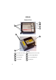
DS2400 General View 1 2 8 3 4 7 5 6 Figure A vi 1 Power ON \ Data Tx LED 5 Warning and Device Class Labels 2 External Trigger LED 6 Laser Beam Output Window 3 Good Read LED 7 Accessory Mounting Holes 4 Laser ON LED 8 Mounting Holes
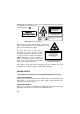
SAFETY PRECAUTIONS LASER SAFETY The following information is provided to comply with the rules imposed by international authorities and refers to the correct use of the DS2400 scanner. Standard Regulations This scanner utilizes a low-power laser diode. Although staring directly at the laser beam momentarily causes no known biological damage, avoid staring at the beam as one would with any very strong light source, such as the sun.
Warning labels indicating exposure to laser light and the device classification are applied onto the body of the scanner (Figure A, 5 ). LASER LIGHT DO NOT STARE INTO BEAM CLASS 2 LASER PRODUCT MAX. OUTPUT RADIATION 1 mW EMITTED WAVE LENGTH 630~680 nm TO IEC 825-1 (1993) CAUTION - LASER LIGHT WHEN OPEN AVOID EXPOSURE TO BEAM R LISTED ACCESSORY 45AF I.T.E. product conforms to the applicable This requirements of 21CFR1040 at the R date of manufacture.
DATALOGIC DS2400 1 GENERAL FEATURES 1.1 INTRODUCTION The DS2400 laser scanner satisfies the most advanced needs of a wide range of users. It has been developed focusing on the realistic requirements of its target market. The outstanding result is an extremely compact, costeffective and easy to use industrial scanner. The DS2400 belongs to the generation of Datalogic scanners that operate under the 'C' programming environment, which is a recognized industry standard.
DS2400 • DATALOGIC completely configurable via serial interface (WinHost). • 2 serial communication interfaces. • supply voltage from 10 to 30 Vdc. • reads all popular codes. • test mode to verify the reading features and exact positioning of the scanner without the need for external tools. • programmable in 4 different operating modes to suit the most various barcode reading system requirements. • code verifier.
DATALOGIC DS2400 1.
DS2400 DATALOGIC 1.4 ACCESSORIES The following accessories are available on request for the DS2400: • 90° deflection mirror GFC-2100 • 20 mA Current Loop interface INT-22 1.5 GFC-2100 ACCESSORY INSTALLATION GFC-2100 is a 90° deflection mirror available on request for DS2400. The installation of the 90° deflection mirror is very easy (Figure 1.1).
DATALOGIC DS2400 2 INSTALLATION 2.1 PACKAGE CONTENTS Verify that the DS2400 reader and all the parts supplied with the equipment are present and intact when opening the packaging; the list of parts includes: 1. 2. 3. 4. 5. DS2400 reader with cable Installation manual Bar code test chart (PCS = 0.9) DS2400 configuration program disk Mounting kit: - bracket - screws * Junction box (for DS2400-XXX1 models only), see par. 1.3. 3 4 2 * 1 5 Figure 2.1 - DS2400 package contents Installation - 2.
DS2400 DATALOGIC 2.2 MECHANICAL INSTALLATION DS2400 can be installed to operate in different positions. The four screw holes (M4 x 5) on the body of the reader are for mechanical fixture (Figure A, 5 ). The diagrams below give the overall dimensions of the scanner and mounting bracket and may be used for installation. Refer to par. 2.5 for correct positioning. Figure 2.2 - DS2400 Overall dimensions 2.
DATALOGIC DS2400 2.3 JUNCTION BOX INSTALLATION The Junction Box provides a passive connection between your scanner and the outside world in a fast and practical way. It represents an alternative to the 25-pin connectors. Figure 2.3 shows the basic layout of a scanner using the junction box. Junction Box DS2400 Scanner cable System cables Figure 2.
DS2400 DATALOGIC The Junction Box is designed to be mounted to a panel of metal, plastic or other appropriate material using the mounting screws provided in the package. To do this: 1) Open the junction box by unscrewing the 4 cover screws. If necessary, using the two mounting holes inside the junction box as a pattern, mark the panel with an appropriate object and then drill two small pilot holes in the panel. Figure 2.
DATALOGIC DS2400 2.3.2 Junction Box Electrical Connections The connection and wiring procedure for Junction Box is described as follows: 1) Open the junction box by unscrewing the 4 cover screws. 2) Pass all System cables through the glands in the junction box housing. 3) To connect the power and input/output signals: • Prepare the individual wires of the system cables by stripping the insulation back approximately 11 mm.
DS2400 DATALOGIC J. Box Pinout for DS2400 Pin Name 01 02 03 04 05 06 07 08 09 10 11 12 13 14 15 16 17 18 19 20 21 22 23 *24 *25 *26 27 28 29 30 31 32 33 34 35 36 37 38 39 18 VS GND VS GND CHASSIS VS VS EXT TRIG + EXT TRIG GND GND VS VS N.C. N.C. GND GND OUT1 + OUT REF OUT2 + N.C. N.C. N.C. Main interface signals see table below 39 1 J1 5 17 Figure 2.7 - Junction Box connector and pinout To allow connection of an NEC Class 2 Power Unit, use a correct female plug adapter.
DATALOGIC DS2400 4) After wiring the junction box and while the scanner is unplugged from the power, place the Scanner cable so that the rubber seal fits into the cutout in the housing of the junction box and plug the 24 pin connector into connector J1 on the PCB inside the junction box as shown in Figure 2.9. Rubber seal J1 Scanner cable Figure 2.
DS2400 DATALOGIC 2.4 ELECTRICAL CONNECTIONS DS2400 25-pin connector models are equipped with a cable terminated by a 25-pin female D-sub connector for connection to the power supply and input/output signals. The details of the connector pins are indicated in the following table: Figure 2.
DATALOGIC DS2400 2.4.1 Power Supply Power can be supplied to the scanner through the pins provided on the 25pin connector used for communication with the host: USER INTERFACE DS2400 13 VS V+ (10 - 30 Vdc) 25 GND 1 CHASSIS VGND CHASSIS Earth Ground Figure 2.11 - Power supply connections The power must be between 10 and 30 Vdc only. It is recommended to connect pin 1 (CHASSIS) to a common earth ground. 2.4.
DS2400 DATALOGIC RS232 Interface The serial interface is used in this case for point to point connections; it handles communication with the host computer and allows both transmission of code data and the programming of the scanner. This is the default setting.
DATALOGIC DS2400 +V RTS -V END OF TRANSMISSION START OF TRANSMISSION DATA TRANSMISSION DATA TRANSMISSION +V TX DATA -V C1 C2 C3 C4 C5 TRANSMISSION STOPPED +V CTS -V ENABLED ENABLED DISABLED IDLE IDLE Figure 2.13 - RS232 control signals If the RTS/CTS handshaking protocol is enabled, the DS2400 activates the RTS232 output to indicate a message is to be transmitted. The receiving unit activates the CTS232 input to enable the transmission.
DS2400 DATALOGIC DS2400 USER INTERFACE 2 TX485+ 4 TX485- 3 RX485+ 5 RX485- 7 SGND + RX485 + TX485 + SGND Figure 2.14 - RS485 full-duplex connections RS485 Half-Duplex Interface The RS485 half-duplex (3 wires + shield) interface is used for polled communication protocols. It can be used in a master/slave layout or for Multidrop connections with a Datalogic Multiplexer, (see par. 2.6.4 and 2.6.5).
DATALOGIC DS2400 Figure 2.16 shows a multidrop configuration with DS2400 scanners connected to a Multiplexer. 120 Ohm max 2 m DS2400 #x (up to 31) max 1200 m DS2400 #1 RTX485 + DS2400 #0 CHASSIS RTX485 SGND Three wires + shield RTX485 + RTX485 MULTIPLEXER RS485 REF SHIELD 120 Ohm Figure 2.
DS2400 DATALOGIC DS2400 USER INTERFACE 5 C.L. IN- 3 C.L. IN+ 4 C.L. OUT- 2 C.L. OUT+ I = 20 mA I = 20 mA MAX. 300 METERS Figure 2.17 - 20 mA C.L. connections 2.4.3 Auxiliary RS232 Interface The auxiliary serial interface is used exclusively for RS232 point to point connections. The parameters relative to the aux interface (baud rate, data bits, etc.
DATALOGIC DS2400 The RTSAUX and CTSAUX signals control data transmission and synchronize the connected devices. If the RTS/CTS handshaking protocol is enabled, the DS2400 activates the RTSAUX output to indicate a message is to be transmitted. The receiving unit activates the CTSAUX input to enable the transmission. 2.4.
DS2400 DATALOGIC DS2400 EXTERNAL TRIGGER VS 9 + 5V V 18 EXT TRIG+ 19 EXT TRIG25 Signal GND Ground Figure 2.20 - Input NPN command using DS2400 power Vext 30 Vdc max. DS2400 EXTERNAL TRIGGER V + 5V Signal 18 EXT TRIG+ 19 EXT TRIGGround Figure 2.21 - Input PNP command using external power EXTERNAL TRIGGER DS2400 9 + 5V VS 18 EXT TRIG+ 19 EXT TRIG- 25 GND V Signal Ground Figure 2.
DATALOGIC DS2400 2.4.5 Outputs There are two general purpose outputs. The following pins are present on the 25-pin connector of the scanner: Pin 8 22 11 12 Name OUT1+ OUT REF OUT2+ OUT REF DS2400 DS2400 11 OUT 2 OUT REF Function Output 1 + Output reference Output 2 + Output reference and/or 12 USER INTERFACE 8 OUT 1 22 OUT REF Vext 40 Vdc max Figure 2.23 Output 1 / Output 2 connections The meaning of the two outputs OUT1 and OUT2 can be defined by the user. Refer to the WinHost Help On Line.
DS2400 DATALOGIC The Pitch angle is represented by the value P in Figure 2.24. Position the reader in order to minimize the Pitch angle. DS2400 Figure 2.24 - Pitch Angle The Skew angle is represented by the value S in Figure 2.25. Position the reader to assure at least 10° for the Skew angle. This avoids the direct reflection of the laser light emitted by the DS2400.
DATALOGIC DS2400 2.6 TYPICAL LAYOUTS The following typical layouts refer to system hardware configurations. Dotted lines in the figures refer to optional hardware configurations within the particular layout. These layouts also require the correct setup of the software configuration parameters. Complete software configuration procedures can be found in the Guide To Rapid Configuration in the WinHost Help On Line. 2.6.
DS2400 DATALOGIC 2.6.2 Pass Through Pass through mode allows two or more devices to be connected to a single external serial interface. Each DS2400 transmits the messages received by the auxiliary interface onto the main interface. All messages will be passed through this chain to the host. When On-Line Operating mode is used, the scanner is activated by an External Trigger (photoelectric sensor) when the object enters its reading zone.
DATALOGIC DS2400 2.6.3 RS232 Master/Slave The RS232 master/slave connection is used to collect data from several scanners to build either an multi-point or a multi-sided reading system; there can be one master and up to 9 slaves connected together. The Slave scanners use RS232 only on the main and auxiliary serial interfaces. Each slave DS2400 transmits the messages received by the auxiliary interface onto the main interface. All messages will be passed through this chain to the master.
DS2400 DATALOGIC 2.6.4 RS485 Master/Slave The RS485 master/slave connection is used to collect data from several scanners to build either a multi-point or a multi-sided reading system; there can be one master and up to 5 slaves connected together. The slave scanners are connected together using RS485 half-duplex on the main serial interface. Every slave scanner must have a multidrop address in the range 0-4. The master scanner is also connected to the Host on the RS232 auxiliary serial interface.
DATALOGIC DS2400 NOTE The auxiliary serial interface of the slave scanners can be used in Local Echo communication mode to control any single scanner (visualize collected data) or to configure it using the WinHost utility or Host Mode Programming procedure. The termination resistors of the RS485 bus must not be installed. 2.6.5 Multiplexer Each scanner is connected to Multiplexer (for example MX4000) with the RS485 half-duplex main interface.
DS2400 DATALOGIC This page is intentionally left blank. 2.
DATALOGIC DS2400 3 READING FEATURES The number of scans performed on the code by the DS2400 and therefore the decoding capability is influenced by the following parameters: • • • • number of scans per second code motion speed label dimensions scan direction with respect to code motion About 5 scans during the code passage should be allowed to ensure a successful read. 3.1 STEP-LADDER MODE If scanning is perpendicular to the code motion direction (Figure 3.
DS2400 DATALOGIC For example, the DS2400 (800 scans/sec.) for a 25 mm high code moving at 1250 mm/s performs: [(25/1250) * 800] - 2 = 14 effective scans. 3.2 PICKET-FENCE MODE If scanning is parallel to the code motion, (Figure 3.
DATALOGIC DS2400 3.3 PERFORMANCE The DS2400 scanner is available in different versions according to the reading performance. 1XXX 2XXX 1XXX 2XXX mm (mils) 0.25 (10) 0.35 (14) scans/s 400 to 1000 400 to 1000 100 mm (4 in) - 440 mm (17 in) on 0.50 mm (20 mils) codes 200 mm (8 in) - 600 mm (23.5 in) on 0.50 mm (20 mils) codes Refer to the diagrams given in par. 3.4 for further details on the reading features.
DS2400 DATALOGIC 3.4 READING DIAGRAMS DS2400-1XXX (Medium Reading Range) 10 20 30 40 50 60 70 cm 20 ≥ 0.50 mm (20 mils) 15 10 0.25 mm (10 mils) 5 0 5 10 15 0.35 mm (14 mils) 20 cm NOTE (0,0) is the center of the laser beam output window. CONDITIONS Code PCS "Pitch" angle "Skew" angle "Tilt" angle Code Resolution* = = = = = = Code Reading Condition* Scanning Speed* = = Interleaved 2/5 or Code 39 0.90 0° 10° 0° High – for 0.25 mm (10 mils) codes and 0.
DATALOGIC DS2400 DS2400-2XXX (Long Reading Range) 10 20 30 40 50 60 70 cm 20 15 10 0.35 mm (14 mils) 5 ≥ 0.50 mm (20 mils) 0 5 10 15 20 cm NOTE (0,0) is the center of the laser beam output window. CONDITIONS Code PCS "Pitch" angle "Skew" angle "Tilt" angle Code Resolution* Code Reading Condition* Scanning Speed* = = = = = = Interleaved 2/5 or Code 39 0.90 0° 10° 0° High - for 0.35 mm (14 mils) codes Standard - for 0.
DS2400 DATALOGIC This page is intentionally left blank. 3.
DATALOGIC DS2400 4 MAINTENANCE 4.1 CLEANING Clean the laser beam output window periodically for continued correct operation of the reader. Dust, dirt, etc. on the window may alter the reading performance. Repeat the operation frequently in particularly dirty environments. Use soft material and alcohol to clean the window and avoid any abrasive substances. WARNING Clean the window of the DS2400 when the scanner is turned off or, at least, when the laser beam is deactivated. Technical Features - 4.
DS2400 DATALOGIC This page is intentionally left blank. 4.
DATALOGIC DS2400 5 TECHNICAL FEATURES DS2400-1XXX DS2400-2XXX ELECTRICAL FEATURES Input Power Supply voltage Power consumption max. 10 to 30 Vdc 5W Serial Interfaces (depends on model) Main RS232; RS485 Full-duplex / Half-duplex; 20 mA C.L. (20 mA C.L. only with INT-22 accessory) Auxiliary RS232 Baud Rates 150 to 115200 Inputs External Trigger Voltage max. Input current max. (optocoupled NPN or PNP) 30 Vdc 25 mA Outputs OUT1, OUT2 VCE max. (optocoupled) 40 Vdc Collector current max.
DS2400 DATALOGIC SOFTWARE FEATURES READABLE CODE SYMBOLOGIES • EAN/UPC (including Add-on 2 and Add-on 5) • 2/5 Interleaved • Code 39 (Standard and Full ASCII) • Codabar Other symbologies available on request.