DS2200 Reference Manual
DS2200 REFERENCE MANUAL
DATALOGIC S.p.A. Via Candini 2 40012 - Lippo di Calderara di Reno Bologna - Italy DS2200 Reference Manual Ed.: 4/2006 ALL RIGHTS RESERVED Datalogic reserves the right to make modifications and improvements without prior notification. Datalogic shall not be liable for technical or editorial errors or omissions contained herein, nor for incidental or consequential damages resulting from the use of this manual.
CONTENTS REFERENCES ............................................................................................. v Conventions .................................................................................................. v Reference Documentation ............................................................................ v Services and Support.................................................................................... v SAFETY PRECAUTIONS......................................................
4 4.1 MAINTENANCE ......................................................................................... 21 Cleaning...................................................................................................... 21 5 TECHNICAL FEATURES ........................................................................... 22 GLOSSARY................................................................................................ 24 INDEX ......................................................................
REFERENCES CONVENTIONS This manual uses the following conventions: “User” or “Operator” refers to anyone using a DS2100A. “Device” refers to the DS2100A. “You” refers to the System Administrator or Technical Support person using this manual to install, mount, operate, maintain or troubleshoot a DS2100A.
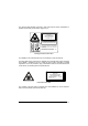
SAFETY PRECAUTIONS LASER SAFETY The following information is provided to comply with the rules imposed by international authorities and refers to the correct use of the DS2200 scanner. Standard Regulations This scanner utilizes a low-power laser diode. Although staring directly at the laser beam momentarily causes no known biological damage, avoid staring at the beam as one would with any very strong light source, such as the sun.
The warning label indicating exposure to laser light and the device classification is applied onto the body of the scanner (Figure A, 8): LASER LIGHT DO NOT STARE INTO BEAM CLASS 2 LASER PRODUCT MAX. OUTPUT RADIATION 1 mW EMITTED WAVELENGTH 630~680 nm TO EN 60825-1:2001 CAUTION-CLASS 3B LASER LIGHT WHEN OPEN AVOID EXPOSURE TO BEAM This product conforms to the applicable requirements of 21CFR1040 at the date of manufacture. DATALOGIC S.p.A.
POWER SUPPLY - This product is intended to be installed by Qualified Personnel only. - DS2200 All Models: This device is intended to be supplied either by a UL Listed NEC Class 2 power source, or a UL listed ITE Limited Power Source (LPS), rated 5Vdc, minimum 0.4A.
GENERAL VIEW DS2200 6 5 4 3 2 7 1 8 Figure A 1 Barcode Image Input Window 5 Ext Trig LED 2 Laser Beam Output Window 6 TX Data LED 3 Power On LED 7 Mounting Holes 4 Good Read LED 8 Laser Warning and Device Class Label ix
GUIDE TO INSTALLATION The following can be used as a checklist to verify all the necessary steps for complete installation of the DS2200 scanner. 1. Read all information in the section "Safety Precautions” at the beginning of this manual. 2. Correctly position and mount the scanner for barcode reading according to the information in par. 2.2, 2.4 and 3.4. 3. Provide correct system cabling according to the signals necessary (see all applicable sub-paragraphs under 2.3). See also sub-paragraphs under 2.
INTRODUCTION 1 1.1 1 INTRODUCTION PRODUCT DESCRIPTION The DS2200 scanner is a cost effective barcode reader complete with decoder designed to satisfy demanding requirements associated with high performance scanning. The DS2200 ultra compact dimensions, based on Datalogic's experience in miniaturized laser components, make the scanner's integration into automated equipment extremely easy.
DS2200 1 A security system allows the laser to activate only once the motor has reached the correct rotational speed; consequently, the laser beam is generated after a slight delay from the power on of the scanner. 1.1.1 Indicators The four LEDs on the scanner indicate the following: POWER ON (red), indicates the reader is connected to the power supply. (Figure A, 3). GOOD READ (red), is used to signal the possibility of a successful barcode reading. (Figure A, 4).
INTRODUCTION 1 The following models are therefore available: DS2200 - X X X X Optical Resolution Reading Window Position 1 = Standard Resolution 2 = High Resolution 0 = Direct Communication Interface Optic Version 1 = RS232 + RS485 0 = Linear 1 = Raster The following tables display each version’s reading performance. Version Max Code Resolution Speed mm (mils) scans/s 1XXX 0.15 (6) 500 2XXX 0.07 (3) 500 Version Reading Distance 1XXX 50 mm (2.0 in) - 220 mm (8.7 in) on 0.
DS2200 2 2 INSTALLATION 2.1 PACKAGE CONTENTS Verify that the DS2200 reader and all the parts supplied with the equipment are present and intact when opening the packaging; the list of parts includes: • DS2200 reader with cable • Installation Manual • Bar code test chart (PCS = 0.
INSTALLATION 2.2 2 MECHANICAL INSTALLATION DS2200 can be installed to operate in any position. There are three screw holes (M2.5 x 5) on the body of the reader for mounting. The diagram below gives all the information required for installation; refer to par. 2.4 for correct positioning of the scanner with respect to the code passage zone. 0.18 3.25 40.5 1.59 50 1.97 8.5 0.33 DS2200 M 2.5 n° 3 8.2* 0.32 33.5 1.32 28 40 1.57 1.10 mm inch The quote refers to the scan line 48.5 40.5 2 6.
DS2200 2 2.2.
INSTALLATION 2.3 2 ELECTRICAL CONNECTIONS The DS2200 cable is equipped with a 25-pin female D-sub connector for connection with the power supply and input/output signals: CAUTION Do not connect GND and SGND to different (external) ground references. GND and SGND are internally connected through filtering circuitry which can be permanently damaged if subjected to voltage drops over 0.8 Vdc.
DS2200 2 2.3.1 Power Supply The following pins of the DS2200 connector are used: DS2200 USER INTERFACE 13/9 VS V+ (5 Vdc) 25 GND GND 1 CHASSIS Figure 4 - Power supply connections The power must be 5 Vdc only. 2.3.2 Main Serial Interface - RS485 Half-Duplex The RS485 half-duplex interface (3 wires + shield) is used for polled communication protocols. It can be used for Multidrop connections in a master/slave layout, or with a Datalogic Multiplexer (see par. 2.5.2 and 2.5.3).
INSTALLATION 2 The following figure shows an example of a multidrop configuration between a Multiplexer and DS2200 scanners. max. 2 m. DS2200 #x (up to 31) DS2200 #1 120 Ohm 5 4 7 5 4 7 Three wires + shield DS2200 #0 max. 1200 m. RTX485+ 5 RTX485- 4 SGND 7 RTX485 + RTX485 MULTIPLEXER RS485 REF SHIELD 120 Ohm Figure 6 - DS2200 Multidrop connection to a Multiplexer 2.3.3 Auxiliary Interface - RS232 The auxiliary serial interface is used exclusively for RS232 point-to-point connections.
DS2200 2 USER INTERFACE DS2200 3 RXAUX 2 TXAUX 7 SGND TXD RXD SGND Figure 7 - RS232 auxiliary interface connections 2.3.4 Inputs The inputs available on the connector supplied with the scanner are indicated below: Pin Name Function 19 22 EXT TRIGI/O REF external trigger (input -) I/O reference The EXT TRIG input is used to connect the external trigger which tells the scanner to scan for a code. The active state of this input is selected in software. Refer to the WinHost Help On Line.
INSTALLATION 2.3.5 2 Outputs Two general purpose outputs are available. These outputs can only be connected as open collector configurations. The following pins are present on the connector of the scanner: Pin Name 8 OUT1+ 11 OUT2+ 10, 12, 22 I/O REF Function output 1 + output 2 + I/O reference The meaning of the two outputs OUT1 and OUT2 can be defined by the user (No Read, Right or Wrong). Refer to the WinHost Help On Line.
DS2200 2 The Pitch angle is represented by the value P in Figure 10. Position the reader in order to minimize the Pitch angle. P Figure 10 - Pitch Angle The Skew angle is represented by the value S in Figure 11. Position the reader to assure about 15° for the Skew angle. This avoids the direct reflection of the laser light emitted by the DS2200. For the raster version, this angle refers to the most inclined or external raster line, so that all other raster lines assure more than 15° Skew.
INSTALLATION 2.5 2 TYPICAL LAYOUTS The following typical layouts refer to system hardware configurations. Dotted lines in the figures refer to optional hardware configurations within the particular layout. These layouts also require the correct setup of the software configuration parameters. Complete software configuration procedures can be found in the Guide To Rapid Configuration in the WinHost Help On Line. 2.5.
DS2200 2 The Master scanner is also connected to the Host on the RS232 auxiliary serial interface. The External Trigger signal is unique to the system; there is a single reading phase and a single message from the Master scanner to the Host computer. It is necessary to bring the External Trigger signal to all the scanners. The main and auxiliary ports are connected as shown in the figure below.
INSTALLATION 2.5.3 2 Multiplexer Each scanner is connected to a Multiplexer (for example MX4000) with the RS485 half-duplex main interface.
DS2200 3 3 READING FEATURES The number of scans performed on the code by the DS2200 and therefore the decoding capability is influenced by the following parameters: • number of scans per second • code motion speed • label dimensions • scan direction with respect to code motion At least 5 scans during the code passage should be allowed to ensure a successful read. 3.
READING FEATURES 3 For example, the DS2200 (500 scans/sec.) for a 25 mm high code moving at 500 mm/s performs: [(25/500) * 500] - 2 = 23 effective scans. 3.
DS2200 3 3.3 PERFORMANCE The DS2200 scanner is available in different versions according to the reading performance. Version 1XXX 2XXX Version Max Code Resolution Speed mm (mils) scans/s 0.15 (6) 0.07 (3) 500 500 Reading Distance 1XXX 50 mm (2.0 in) - 220 mm (8.7 in) on 0.60 mm (24 mils) codes 2XXX 40 mm (1.6 in) - 125 mm (4.9 in) on 0.20 mm (8 mils) codes Refer to the diagrams given in par. 3.4 for further details on the reading features.
READING FEATURES 3.4 3 READING DIAGRAMS The following diagrams show the reading distance for barcodes with different densities. DS2200-1XXX (Standard Resolution) 0 1 0 5 20 2 40 3 60 4 5 6 7 8 9 10 (in) 80 100 120 140 160 180 200 220 240 260 (mm) 120 4 100 3 80 60 2 40 1 20 0 0 1 20 2 40 60 3 80 4 100 5 (in) 120 0.15 mm (6 mils) 0.20 mm (8 mils) 0.30 mm (12 mils) 0.50 mm (20 mils) ≥ 0.
DS2200 3 DS2200-2XXX (High Resolution) 0 1 0 10 20 2 30 40 50 3 60 70 4 80 5 90 100 110 120 130 60 2 50 40 30 1 20 10 0 0 10 20 1 30 40 2 (in) 50 0.10 mm (4 mils) 60 (mm) 0.12 mm (5 mils) NOTE: (0,0) is the center of the laser beam output window. CONDITIONS: Code PCS "Pitch" angle "Skew" angle "Tilt" angle 20 = = = = = Interleaved 2/5 or Code 39 0.90 0° 15° 0° 0.15 mm (6 mils) ≥ 0.
MAINTENANCE 4 4.1 4 MAINTENANCE CLEANING Clean the windows periodically for continued correct operation of the reader. Dust, dirt, etc. on the windows may alter the reading performance. Repeat the operation frequently in particularly dirty environments. Use soft material and alcohol to clean the windows and avoid any abrasive substances. Clean the windows of the DS2200 when the scanner is turned off or, at least, when the laser beam is deactivated.
DS2200 5 5 TECHNICAL FEATURES DS2200-1XXX DS2200-2XXX ELECTRICAL FEATURES Power Maximum input voltage Power consumption max. 5 Vdc ± 5% 2W Serial Interfaces Main Auxiliary Baud Rates Inputs Outputs VCE max. Collector current max. VCE saturation Power dissipation max. RS485 Half-Duplex RS232 150 to 115200 External Trigger User-defined OUT1 and OUT2 50 Vdc 50 mA continuous 0.3V at 10 mA max. 200 mW at 40 °C (Ambient temp.
TECHNICAL FEATURES 5 SOFTWARE FEATURES READABLE CODE SYMBOLOGIES • EAN/UPC (including Add-on 2 and Add-on 5) • 2/5 Interleaved • Code 39 (Standard and Full ASCII) • Codabar Other symbologies available on request Code Selection Decoding Safety Headers and Terminators Operating Modes Configuration Modes Parameter Storage • Code 93 • Code 128 • EAN 128 • Pharmacode up to six codes during one reading phase can enable multiple good reads of same code up to four headers and four terminators On Line, Automatic
GLOSSARY Aperture Term used on the required CDRH warning labels to describe the laser exit window. Barcode A pattern of variable-width bars and spaces which represents numeric or alphanumeric data in machine-readable form. The general format of a barcode symbol consists of a leading margin, start character, data or message character, check character (if any), stop character, and trailing margin. Within this framework, each recognizable symbology uses its own unique format.
EEPROM Electrically Erasable Programmable Read-Only Memory. An on-board non-volatile memory chip. Full Duplex Simultaneous, two-way, independent transmission in both directions. Half Duplex Transmission in either direction, but not simultaneously. Host A computer that serves other terminals in a network, providing services such as network control, database access, special programs, supervisory programs, or programming languages.
Protocol A formal set of conventions governing the formatting and relative timing of message exchange between two communicating systems. Raster The process of projecting the laser beam at varied angles spaced evenly from each other. Typically, the mirrored rotor surfaces are angled to create multiple scan lines instead of a single beam. Resolution The narrowest element dimension which can be distinguished by a particular reading device or printed with a particular device or method.
Symbol A combination of characters including start/stop and checksum characters, as required, that form a complete scannable barcode. Tilt Rotation around the Z axis. Used to describe the position of the barcode with respect to the laser scan line. See pars. 2.2.1 and 2.4. Trigger Signal A signal, typically provided by a photoelectric sensor or proximity switch, which informs the scanner of the presence of an object within its reading zone. UPC Acronym for Universal Product Code.
INDEX A Accessories; 3 C Cleaning; 21 E Electrical Connections; 7 G General View; ix Glossary; 24 Guide to Installation; x I Inputs; 10 Installation; 4 Interfaces Auxiliary – RS232; 9 Main – RS485 Half Duplex; 8 L Laser Safety; vi LED Indicators; 2 M Maintenance; 21 Model Description; 2 Mounting DS2200; 6 28 O Outputs; 11 P Package Contents; 4 Performance; 18 Picket-Fence Mode; 17 Positioning; 11 Power Supply; viii R Raster; 18 Reading Diagrams; 19 Reading Features; 16 Reference Documentation; v S Servic
DATALOGIC S.p.A.