
DL Cordless Card Reference Manual


TYPICAL SYSTEM LAYOUTS
A
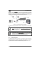
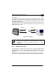
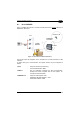
A.1 DLCC SERVER
DLCC is installed into a Rhino™ vehicle mounted terminal and
receives data from a
DRAGON™ M scanner.
DRAGON™ M
A.P.
433 MHz RF
Connection
2.4 GHz
Network
Wired
LAN
RHINO™
DLCC
Figure 11 - DLCC Server Installed into Rhino™
This layout shows the integration of the 433 MHz and 2.4 GHz networks for data
collection.
To define this type of communication, the system devices may be configured as
follows:
DLCC
- Setup for Server Only Functioning
- DLCC Radio Address = 0017
RHINO™
- Run an application managing the data communication
between the mobile computer and the host system, for
example Terminal Emulation.
DRAGON™ M
- Setup for STAR-System mode
- DRAGON™ M Radio Address = 1235
- Destination Address = 0017
35