DL Cordless Card TM www.mobile.datalogic.com World wide Sales Network available from: www.mobile.datalogic.com/contacts Datalogic Mobile S.r.l. Via S. Vitalino, 13 40012 Lippo di Calderara di Reno Bologna - Italy Telephone: (+39) 051-3147011 Fax: (+39) 051-3147561 Reference Manual ©2002-2007 Datalogic Mobile S.r.l.
Datalogic Mobile S.r.l. Via S. Vitalino 13 40012 - Lippo di Calderara di Reno Bologna - Italy DL Cordless Card™ Ed.: 09/2007 This manual refers to software version 1.0 and later ALL RIGHT RESERVED Datalogic reserves the right to make modifications or improvements without prior modifications. Datalogic shall not be liable for technical or editorial errors or omissions contained herein, nor for incidental or consequential damages resulting from the use of this material.
CONTENTS REFERENCES ............................................................................................. v Conventions .................................................................................................. v Reference Documentation ............................................................................ v Services and Support.................................................................................... v COMPLIANCE..............................................................
.4.5 4.4.6 ACK/NACK From Remote Host (Client only) .............................................. 30 Beacon (Client only).................................................................................... 31 5 DEFAULT CONFIGURATION .................................................................... 32 6 TECHNICAL FEATURES ........................................................................... 33 A A.1 A.2 TYPICAL SYSTEM LAYOUTS...................................................................
REFERENCES CONVENTIONS This manual uses the following conventions: "User" refers to anyone using a DL Cordless Card™. "DLCC" refers to the DL Cordless Card™. "You" refers to the System Administrator or Technical Support person using this manual to install, configure, operate, maintain or troubleshoot a DLCC. REFERENCE DOCUMENTATION For further details refer to the card Quick Reference Manual and to the RHINO™ Reference Manual.
COMPLIANCE RADIO COMPLIANCE Contact the competent authority responsible for the management of radio frequency devices of your country to verify the eventual necessity of a user license. Refer to the web site http://europa.eu.int/comm/enterprise/rtte/spectr.htm for further information.
Information for the user in accordance with the European Commission Directive 2002/96/EC At the end of its useful life, the product marked with the crossed out wheeled wastebin must be disposed of separately from urban waste. Disposing of the product according to this Directive: avoids potentially negative consequences to the environment and human health which otherwise could be caused by incorrect disposal enables the recovery of materials to obtain a significant savings of energy and resources.
Benutzerinformation bezüglich Richtlinie 2002/96/EC der europäischen Kommission Am Ende des Gerätelebenszyklus darf das Produkt nicht über den städtischen Hausmüll entsorgt werden. Eine entsprechende Mülltrennung ist erforderlich.
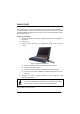
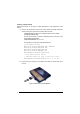
QUICK START The following can be used as a checklist to verify all of the steps necessary for complete installation of the DL Cordless Card™ for a DOS terminal and for a laptop (with two PCMCIA overlaid slots for PC cards of type II and with Windows 98, ME, XP, and later versions). Installing to portable PC 1) Read all information in the section "Safety Precautions" at the beginning of this manual. 2) Start your PC. 3) Insert the DLCC correctly in the PCMCIA slot. Refer to the PC user's manual.
Installing to DOS Terminal Read all information in the section "Safety Precautions" at the beginning of this manual. 1) Rhino™ will recognize the card if the correct drivers are loaded. Therefore, before inserting the card into the terminal make sure that: - in NEWCFG.SYS the driver for the PCMCIA serial ports is loaded: A:\PCMCIA\PCMSCD.EXE - the scan engine driver is correctly configured (COM 3, interrupt 5) and loaded after PCMSCD.EXE: A:\DRIVERS\REDIR.
3) Start the DOS terminal. The system assigns DLCC a virtual COM port (COM 3, interrupt 5). 4) Configure the DLCC address according to your application. See "Configuration Methods" paragraph. The default communication parameters of the COM port are: 9600 baud, no parity, 8 data bits, 1 stop bit, handshaking disabled NOTE The installation is now complete.
CONFIGURATION METHODS DLCC configuration can be performed by four methods: • DL Mobile Configurator™ to set the primary DLCC parameters; • DL Sm@rtSet™ software configuration program; • configuration strings sent from the Host via COM port; • DLCARD.EXE DOS configuration of DLCC.
DLCARD.EXE DOS Configuration Program This configuration method allows setting DLCC through a vehicle mounted terminal running the DOS operating system. Upon start, the DOS DLCARD.EXE program checks communication with DLCC. If the test is successful, the program will open the file DLCARD.INI that includes a list of keywords.
xiv
INTRODUCTION 1 1 INTRODUCTION The DL Cordless Card™ is a PCMCIA card developed to provide wireless 433 MHz RF communication between a laptop or a vehicle mounted terminal (Host) and Datalogic RF devices or base stations, which are STAR-System™ compatible: - Gryphon™ M Readers - Dragon™ M Laser Scanners - STAR Modem™ Radio Modems - Formula Basic Line RF Terminals (F734-E/RF, F725-E/RF, F660-E/RF) - STARGATE™ Base Stations 1.
DL CORDLESS CARD 1 1.2 LED INDICATOR DL Cordless Card™ has one red LED as displayed in the following figure: LED Indicator Figure 4 - DLCC LED Indicator The LED signals activity on PCMCIA interface.
INITIAL SETUP 2 2 INITIAL SETUP For a correct DLCC configuration keep in mind the following: • when using the DLCC for the first time, set the desired card address via COM Port, since its factory default address is "Undefined"; 2.1 CONFIGURATION STRINGS When using a DLCC on a terminal or a portable PC, initial setup can be performed via COM port by sending the configuration strings to the card using any terminal emulation program, for example Hyper Terminal.
DL CORDLESS CARD™ 2 2.2 DLCC SETUP RESTORE DEFAULT Whenever necessary, send the following string to DLCC via COM Port to restore its default values. Otherwise skip to step 2: 1. Restore DLCC Default $+$*CR This command does not change the DLCC address nor the destination device addresses, nor the RF Baud Rate parameters.
CONFIGURATION 3 3 CONFIGURATION Once the card is setup, you can change the default parameters to meet your application needs by sending the desired strings to the card via COM Port.
COM PORT PARAMETERS BAUD RATE PARITY DATA BITS STOP BITS HANDSHAKING ACK/NACK PROTOCOL FIFO INTER-CHARACTER DELAY RX TIMEOUT FRAME PACKING The programming sequence is the following: $+ Command $- CR Carriage return character (0D Hex.
COM PORT Description String BAUD RATE 150 baud CD0 300 baud CD1 600 baud CD2 1200 baud CD3 2400 baud CD4 4800 baud CD5 9600 baud CD6 19200 baud CD7 38400 baud CD8 57600 baud CD9 PARITY None CC0 Even parity CC1 Odd parity CC2 DATA BITS 7 bits CA0 8 bits CA1 9 bits CA2 STOP BITS 1 bit CB0 2 bits CB1 7
COM PORT Description HANDSHAKING String see par. 4.2.1 Disable CE0 Hardware (RTS/CTS) CE1 Software (XON/XOFF) CE2 RTS always ON CE3 Modem (RTS/CTS) CE4 ACK/NACK PROTOCOL see par. 4.2.2 Disabled ER0 Enable ACK/NACK ER1 Enable DATA/NACK ER2 FIFO see par. 4.2.4 Disable ME1 Enable ME0 INTER-CHARACTER DELAY CK00 – CK99 Inter-character delay (ms) RX TIMEOUT see par. 4.2.3 and par. 4.2.5 CL00 – CL99 RX Timeout (sec) FRAME PACKING see par. 4.2.
DATA FORMAT HEADER TERMINATOR HEADER POSITION CODE LENGTH TX ADDRESS STAMPING ADDRESS DELIMITER The programming sequence is the following: $+ Command $- CR Carriage return character (0D Hex.
DATA FORMAT Description String HEADER EA00 No header One character header EA01x Two character headers EA02xx Three character headers EA03xxx Four character headers EA04xxxx Five character headers EA05xxxxx Six character headers EA06xxxxxx Seven character headers EA07xxxxxxx Eight character headers EA08xxxxxxxx TERMINATOR EA10 No terminator One character terminator EA11x Two character terminators EA12xx Three character terminators EA13xxx Four character terminators EA14xxxx Five c
DATA FORMAT Description HEADER POSITION String see par. 4.3.1 First frame field ES0 Before message field ES1 CODE LENGTH TX Code length not transmitted EE0 Code length transmitted in variable-digit length EE1 Code length transmitted in fixed 4-digit format EE2 The code length is transmitted in the message after the Headers and Code Identifier characters. The code length is calculated after performing any field adjustment operations. ADDRESS STAMPING see par. 4.3.
RADIO PARAMETERS RF BAUD RATE TRANSMISSION MODE RADIO PROTOCOL TIMEOUT SINGLE STORE ACK/NACK FROM REMOTE HOST BEACON The programming sequence is the following: $+ Command $- CR Carriage return character (0D Hex.
RADIO PARAMETERS Description RF BAUD RATE String see par. 4.4.1 9600 baud MF0 19200 baud MF1 TRANSMISSION MODE (Client only) see par. 4.4.2 1 way mode MW0 2 way mode MW1 RADIO PROTOCOL TIMEOUT (Client only) see par. 4.4.3 MH01 – MH19 Radio protocol timeout (seconds) SINGLE STORE (Client only) see par. 4.4.
RADIO PARAMETERS Description String ACK/NACK FROM REMOTE HOST (Client only) see par. 4.4.5 Disabled MR0 Enable ACK/DATA/NACK MR1 BEACON (Client only) see par. 4.4.
PARAMETER ISSUES AND DEFINITIONS 4 4 PARAMETER ISSUES AND DEFINITIONS 4.1 RADIO AND SERIAL COMMUNICATION CONTROLS DLCC communication can be controlled by several parameters depending on whether it is a Client or Server. DLCC can act as both Client and Server. The following table summarizes which parameters are controlled by the Client and which ones are controlled by the Server.
DL CORDLESS CARD™ 4 Case 1 – DLCC as Server DRAGON 1 HOST DRAGON 2 DRAGON 3 DLCC F734-E Figure 5 –DLCC as Server DLCC as a Server receives data from RF devices. The ACK/NACK Protocol parameter can be set to assure correct communication between DLCC and the local Host.
PARAMETER ISSUES AND DEFINITIONS 4 Case 2 – DLCC as Client (like an RF device) HOST Client Figure 6 - DLCC Client In the figure above, DLCC is a Client (as an RF device). The following parameters may be set depending on the application: STAR Modem™ - ACK/NACK = enabled STAR-System™ - Rx / Tx = enabled • If DLCC - Transmission Mode = 1 way ACK/NACK from Remote Host = disabled FIFO = disabled Handshaking = modem (RTS/CTS) In this case, DLCC sends data (messages) to the Remote Host.
DL CORDLESS CARD™ 4 Case 3 – DLCC as Client / Server Client Server HOST 1 HOST 2 Figure 7 – DLCC as Client / Server Both DLCCs are able to communicate bi-directionally. For analysis purposes only, we assume the situation where Host 1 is Client and Host 2 is Server.
PARAMETER ISSUES AND DEFINITIONS • If DLCC 1 - 4 Transmission Mode = 2 ways ACK/NACK from Remote Host = enabled FIFO = enabled Handshaking = any Single Store = enabled The Client, (Host 1) sends a message to the Remote Host (Host 2) and expects an answer from Host 2. Host 2 answers with DATA (a string of up to 238 characters). If DLCC 2 sends this DATA answer within the Radio Protocol Timeout, DLCC 1 sends it to its local Host (Host 1), otherwise DLCC 1 sends NACK.
DL CORDLESS CARD™ 4 4.2 4.2.1 COM PORT PARAMETERS Handshaking Modem: (RTS/CTS) DLCC deactivates the RTS line when it cannot receive a character from the Host. DLCC can transmit data only if the CTS line (controlled by the Host) is active.
PARAMETER ISSUES AND DEFINITIONS 4 Hardware handshaking: (RTS/CTS) The RTS line is activated by DLCC before transmitting a character. Transmission is possible only if the CTS line (controlled by the Host) is active.
DL CORDLESS CARD™ 4 4.2.2 ACK/NACK Protocol This parameter sets a transmission protocol which takes place between DLCC (Server) and an RF device. An RF device (such as a hand-held reader) passes its data (code read) to the card installed into the terminal. The Host sends an ACK character (06 HEX) to the card in the case of good reception; a NACK character (15 HEX) requesting re-transmission is sent to the card in case of bad reception.
PARAMETER ISSUES AND DEFINITIONS 4 If the card does not receive an ACK, DATA or NACK, transmission is ended after the RX Timeout (see par. 4.2.3 ). See also Radio Protocol Timeout, par. 4.4.3, for radio transmission to RF devices. For ACK/NACK selection when DLCC as Client, is transmitting to a destination device connected to a Remote Host, refer to par. 4.1. 4.2.3 RX Timeout This parameter can be used to automatically end data reception from the Local Host after the specified period of time.
DL CORDLESS CARD™ 4 4.2.5 Frame Packing This parameter defines the format of the frame to be transmitted between DLCC and the Host. The frame received by DLCC may contain a maximum of 238 characters. All characters not included within this number will be transmitted from the Host in a new frame.
PARAMETER ISSUES AND DEFINITIONS 4 Correct FRAME identification is managed by frame packing. Three different types of frame packing can be selected: • Frame+ [CR] (default): the frame sent to DLCC is terminated by [CR]. This means you cannot use the [CR] character within the frame. In Frame + [CR] mode, make sure the FRAME does not contain [CR], nor begin with $+ or #+ characters. FRAME [CR] The frame transmitted by DLCC has no additional field.
DL CORDLESS CARD™ 4 This string is always transmitted in a single frame preceding the one containing the configuration command, as shown in the following examples: Example 1 Sending the $+$![CR] command to transmit the card software release: st 1 Frame = #+++PROG_REQ+++# nd 2 Frame = $![CR] Example 2 Sending the $+ML0$-[CR] command to set the default frame packing configuration: st 1 Frame = #+++PROG_REQ+++# nd 2 Frame = ML0$-[CR] 4.3 DATA FORMAT 4.3.
PARAMETER ISSUES AND DEFINITIONS 4.3.2 4 Address Stamping If enabled, this command includes the RF device or DLCC address in the message/answer transmitted. It is advised to enable this parameter when DLCC is a Server for more than one Client in 2 way transmission. In this way the Host knows to which Client the answer must be sent. If receiving data from an RF device working in 1 way mode, DLCC (Server) automatically includes the RF device address in the message to be sent to the Host.
DL CORDLESS CARD™ 4 If DLCC as Client, is transmitting to more than one destination device (see the three Stargates in the following figure) in 2 way mode, it is necessary to set its Host application to include the card address in the message to be transmitted to the destination devices of the system. DLCC will include the same address in the answer it receives from the destination devices and sends back to the Host. Card Addr. + message Card Addr.
PARAMETER ISSUES AND DEFINITIONS 4.4 4 RADIO PARAMETERS 4.4.1 RF Baud Rate This parameter defines the baud rate used for radio communication. The baud rate value can be set to 9600 or 19200 according to the device communicating with DLCC. 19200 is the default value. 4.4.
DL CORDLESS CARD™ 4 Once the transmission is successful, the card continues to send new messages. If transmission is not successful after the number of configured attempts, the message is lost. To be absolutely sure that messages are received by the destination device, set Single Store to continuous. A new message will not be sent unless the previous one is received.
PARAMETER ISSUES AND DEFINITIONS 4 Two way mode: Host sends a message to DLCC which passes it to the destination device via radio. The destination device transmits the message to the Remote Host which responds with DATA. This answer is sent to DLCC through the destination device. Then, the card transmits it to the Host. If the Radio Protocol Timeout expires before the answer from Remote Host is received by DLCC or in case the Remote Host does not respond, DLCC sends a NACK character to the Host.
DL CORDLESS CARD™ 5 5 DEFAULT CONFIGURATION Configuration Parameter Default Setting Serial Communication Baud Rate Parity, Data Bits, Stop Bits Handshaking ACK/NACK Protocol FIFO Intercharacter Delay RX Timeout Frame Packing 9600 No parity; 8 Data bits; 1 Stop bit Disabled Disabled Enabled Disabled 5 seconds Frame +[CR] Data Format Header Terminator Header Position Code Length TX Address Stamping Address Delimiter No headers [CR] and [LF] First frame field Code Length not Transmitted Disabled Disabl
TECHNICAL FEATURES 6 6 TECHNICAL FEATURES Electrical Features Supply voltage Power consumption Indicator 5 Vdc ± 3% 400 mW One red LED Radio Features Working frequency Bit rate Effective Radiated Power Range (in open air) RF Modulation 433.92 Mhz Up to 19200 baud <10 mW 15 m / 49.
DL CORDLESS CARD™ A A TYPICAL SYSTEM LAYOUTS The following examples give a graphical representation of DLCC applications in 2 typical layouts and provide the software configuration required by each device to communicate within the system (see par. 4.1 for details about the main parameter functioning).
TYPICAL SYSTEM LAYOUTS A.1 A DLCC SERVER DLCC is installed into a Rhino™ vehicle mounted terminal and receives data from a DRAGON™ M scanner. DRAGON™ M A.P. 433 MHz RF Connection 2.4 GHz Network Wired LAN RHINO™ DLCC Figure 11 - DLCC Server Installed into Rhino™ This layout shows the integration of the 433 MHz and 2.4 GHz networks for data collection.
DL CORDLESS CARD™ A A.2 BI-DIRECTIONAL COMMUNICATION Two DLCCs are installed into the dedicated Host. They communicate with each other by transmitting and receiving data.
HEX AND NUMERIC TABLE B B HEX AND NUMERIC TABLE CHARACTER TO HEX CONVERSION TABLE char hex char hex char hex NUL SOH STX ETX EOT ENQ ACK BEL BS HT LF VT FF CR SO SI DLE DC1 DC2 DC3 DC4 NAK SYN ETB CAN EM SUB ESC FS GS RS US SPACE ! " # $ % & ' ( ) 00 01 02 03 04 05 06 07 08 09 0A 0B 0C 0D 0E 0F 10 11 12 13 14 15 16 17 18 19 1A 1B 1C 1D 1E 1F 20 21 22 23 24 25 26 27 28 29 * + , .
GLOSSARY 1 way transmission a radio transmission in which DLCC transmits data without requiring an acknowledgement answer from the remote Host. 2 way transmission a radio transmission in which DLCC transmits data requiring an acknowledgement answer from the remote Host. Client a radio device which can initiate a 1 way or 2 way transmission to a Server. The Client is also defined as Transmitter. DLCC, RF terminals or RF hand-held readers function as Clients.
INDEX C COM Port Parameters; 20 ACK/NACK Protocol; 22 Handshaking; 20 Compliance; vi Configuration; 5 COM Port Parameters; 6 Data Format; 9 Radio Parameters; 12 Configuration Methods; xii Configuration Strings from Host; xii DL Mobile Configurator™; xii DL Sm@rtSet™; xii DLCARD.
Datalogic Mobile S.r.l. Via S.
DL Cordless Card TM www.mobile.datalogic.com World wide Sales Network available from: www.mobile.datalogic.com/contacts Datalogic Mobile S.r.l. Via S. Vitalino, 13 40012 Lippo di Calderara di Reno Bologna - Italy Telephone: (+39) 051-3147011 Fax: (+39) 051-3147561 Reference Manual ©2002-2007 Datalogic Mobile S.r.l.