SC6000 Reference Manual
SC6000 REFERENCE MANUAL
DATALOGIC S.p.A. Via Candini 2 40012 - Lippo di Calderara di Reno Bologna - Italy SC6000 Reference Manual Ed.: 10/2005 ALL RIGHTS RESERVED Datalogic reserves the right to make modifications or improvements without prior notification. Datalogic shall not be liable for technical or editorial errors or omissions contained herein, nor for incidental or consequential damages resulting from the use of this material.
CONTENTS REFERENCES ............................................................................................................. v Reference Documentation ............................................................................................ v Services and Support ................................................................................................... v SAFETY REGULATIONS ........................................................................................... vi Power Supply...........
Main Interface ............................................................................................................. 39 Extended I/O............................................................................................................... 41 Modem........................................................................................................................ 44 GLOSSARY................................................................................................................
REFERENCES REFERENCE DOCUMENTATION The documentation related to the SC6000 is listed below: • PWO power supply unit • Document about the Ethernet connectivity • Document about the Profibus connectivity • Guide to Installing a Redundant System • Replacing an SC8000 Controller • Help On-Line in PDF format SERVICES AND SUPPORT Datalogic provides several services as well as technical support through its website. Log on to www.datalogic.
SAFETY REGULATIONS POWER SUPPLY - This product is intended to be installed by Qualified Personnel only.
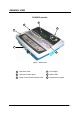
GENERAL VIEW SC6000 Controller 4 3 5 2 1 6 Figure 1 - General View 1 Connector Panel 4 LCD Display 2 Connector Panel Legend 5 Status LEDs 3 Power On and Communication LEDs 6 Programming Keypad vii
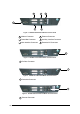
2 3 4 1 6 5 Figure 2 - SC6000-1200 Standard Model Connector Panel 1 Modem Connector 4 Ethernet Connector 2 Power/Net Connector 5 Auxiliary Interface Connector 3 Main Interface Connector 6 Extended I/O Connector 1 Figure 3 - SC6000-1211 Profibus Model Connector Panel 1 Profibus Connector 1 Figure 4 - SC6000-1215 DeviceNet Model Connector Panel 1 DeviceNet Connector 1 Figure 5 - SC6000-1230 Dual Ethernet Model Connector Panel 1 Ethernet Connector viii
GUIDE TO INSTALLATION The following can be used as a checklist to verify all the steps necessary to complete installation of the SC6000 Controller. 1) Read all information in the section “Safety Precautions” at the beginning of this manual. 2) Correctly mount the SC6000 using the bracket provided according to the information in par. 2.3. 3) Connect the SC6000 Controller to the PWO by means of the appropriate accessory cables (see par. 1.4).
x
INTRODUCTION 1 1 INTRODUCTION 1.1 PRODUCT DESCRIPTION The new SC6000 Controller offers all the necessary functions to make the phases of installation, setup, testing, and maintenance of the omni-directional reading tunnel easy and quick.
SC6000 1 1.
INTRODUCTION 1 1.
SC6000 2 2 INSTALLATION To install the system follow the given procedure: 1) Select the mounting location and mount the SC6000 Controller; 2) Mount the PWO (refer to the PWO Installation Manual); 3) Proceed with system electrical connections; 4) Install the GENIUS™ program on the configuration PC. If your system requires the SC6000 to be connected to PWO refer to the Reference Documentation section for details. NOTE 2.
INSTALLATION 2 2.2 OVERALL DIMENSIONS 39.7 [1.56] 124.4 [4.90] 99.7 [3.93] MØ8 248.7 [9.79] 124.4 [4.90] 39.7 [1.56] 80.2 [3.16] 319.5 [12.58] 298 [11.73] mm inch Figure 8 - SC6000 Overall Dimensions N° [R 2 R 0. 1 59 5 ] 300 [11.80] 48 [1.89] 16 [0.63] N°6 8 [0.32] N°2 R10 [R0.39] 180 [7.09] 50 [1.97] 5 [0.20] 30 [1.18] 16 [0.63] 15 [0.59] M8 309 [12.17] 85 [3.35] 85 [3.35] mm inch 40 [1.57] 48 [1.89] 40 [1.57] 40 [1.57] 56 2Ø N° 2.22] [Ø [0 8 .3 3] 15 [0.59] 95 [3.
SC6000 2 2.3 MECHANICAL MOUNTING To mount the SC6000 Controller on the reading station frame proceed as follows: 1 Mount the bracket on the reading station frame: the slots on the bracket will help obtain the best positioning. When working in environments characterized by strong vibrations, set the screws as close as possible to the bracket edges, see Figure 10. 2 Tighten the ST-222 bracket to the reading station frame using the screws and washers.
INSTALLATION 2 The specially punched steel ring has been designed to obtain the most precise rotation possible in terms of angle calibration, steadiness and consequent absence of torque between both sides of device. 5 Place a locking washer and then a flat washer onto each knob. Tighten the SC6000 Controller to its bracket by screwing the knobs into their holes - one on each side.
SC6000 2 2.4 ELECTRICAL CONNECTIONS The connectors available for each scanner model are the following: Scanner Model All models - 1230 1211 1215 2.4.
INSTALLATION 2.4.2 2 Ethernet Connector This connector is available for all SC6000 Controller models and allows the Ethernet connection to the host. In the SC6000-1230 Dual Ethernet there are two Ethernet connectors for secondary host connections. RJ45 Modular Jack Pinout Pin 1 2 3 6 4, 5, 7, 8 Name TX + TX RX + RX N.C.
SC6000 2 Ethernet Interface The Ethernet interface (NIC) can be used for TCP/IP communication with a remote or local host computer by connecting the SC6000 Controller to a LAN or directly to a host PC. The following is an example of a connection to a LAN through a Hub using a straight through cable: SC6000 HUB / SWITCH TX+ 1 1 TX- 2 2 RX+ 3 3 n. c. 4 4 n. c. 5 5 RX- 6 6 n. c. 7 7 n. c. 8 8 n. c.
INSTALLATION 2.4.
SC6000 2 2.4.4 Profibus Connector The 9-pin female Profibus connector (white) is only available in the SC6000-1211 Profibus model and allows connection between the host and the controller: 1 5 9 6 Figure 20 - Profibus 9-pin Female Connector 9-pin D-sub Female Profibus connector pinout Pin 1 2 3 4 5 6 7 8 9 Name Shield* N.C. B-LINE (RxD/TxD-P) CNTR-P** DGND +5 V N.C. A-LINE (RxD/TxD-N) CNTR-N** * signal is optional ** signal is optional; RS485 level Function Shield, protective ground resp.
INSTALLATION 2 2.5 TYPICAL LAYOUTS The following typical layouts refer to system hardware configurations, but also require the correct setup of the software configuration parameters (see par. 3.2 for details). Other layouts require the use of a specific SC6000 Controller model. The accessories and cables indicated in the following figures are Datalogic products. We suggest their use to guarantee the correct system functioning. 2.5.
SC6000 2 Figure 23 - Modem Connection 2.5.2 Fieldbus Network The SC6000 can be connected to a Fieldbus network (Ethernet, Profibus and DeviceNet) to communicate with a remote host (for example, remote PC connected via Internet). Connections are made directly through cables to the Fieldbus connector and do not require any converter or adapter.
INSTALLATION 2 Figure 25 - Dual Ethernet Connection 2.6 KEYPAD AND DISPLAY The SC6000 keypad allows entering a menu to select one of the functions described in the following paragraphs. 2.6.1 Standard Mode Upon startup, the diagnostic mask window is visualized by default.
SC6000 2 Reading Performance Window This window displays the following data: • Number of the processed parcels • Good Read Rate • No Read Rate • Multiple Read Rate Reading Mask Window This window indicates the node that performed a reading of the codes enabled on the master. The following indicators are used: "*" "-" The node read a barcode enabled on the master. The node read no barcode. I/O Status Window This window provides data concerning the conveyor speed and the digital input/output status.
SOFTWARE CONFIGURATION 3 3 SOFTWARE CONFIGURATION 3.1 GENIUS™ INSTALLATION Genius™ is a new Datalogic scanner configuration tool providing several important advantages: • Multi-language version; • Defined configuration directly stored in the device; • Communication protocol independent from the physical interface allowing to consider the device as a remote object to be configured and monitored.
SC6000 3 2. From the Device Menu select Local Device Network Settings and configure your SC6000 as Master (SYNCHRONIZED is the default value), as shown in the figure below: Figure 27 – Local Device Network Settings The following dialog box appears asking whether to send the configuration to the Master or not: icon available on the Toolbar to make the 3. Click the "Yes" button, then click on the “Devices” area appear next to the Parameter Explorer window.
SOFTWARE CONFIGURATION 3 Each device is indicated by the following graphical objects: • • • check box allowing to select/deselect a specific device to perform the desired operations (i.e. program downloading); icon representing the device status; a label reporting information transmitted by the device when connected (the device address, generated errors, device description). 4. Then, proceed with the Network Setup (par. 3.2.1). 5.
SC6000 3 Proceed with the network setup by using one of the icons available on the Tool Bar according to the procedure to follow: = Net-Autoset procedure = Network Wizard procedure = Express Network Setup procedure Net-Autoset This procedure is to be used when all scanner addresses and labels are unknown (typically when configuring the network for the first time or whenever a network reconfiguration is required).
SOFTWARE CONFIGURATION 3 Network Wizard Before performing this procedure, a Lonworks address must be assigned to each slave scanner. The most practical method is through the Net-Autoset procedure. See par. 3.2.2 for alternative address assignment methods. Once all addresses have been assigned, the Network Wizard is to be used when one or more scanner addresses and labels need to be modified. 1. Click on the button to open the Network Wizard dialog box: a.
SC6000 3 2. If desired, select a slave scanner within the "Current Devices" area and click on the icon (or select the "Show Device" option from the right-click menu) to make the dialog box appear as follows: • • The "Show Device" option is particularly useful after the Net-Autoset procedure or whenever it is necessary to know which address is assigned to a specific slave scanner.
SOFTWARE CONFIGURATION 3.2.2 3 Alternative Slave Address Assignment As alternatives to Network Setup through the Master, each Slave scanner can be assigned an address through the following methods: • random address assignment from SC6000 to all slaves in the network by performing the CASP™ procedure as described in par. 2.6.
SC6000 3 4) From the Device Menu select Local Device Network Settings and configure your SC6000 as Other, as shown in the figure below: Figure 30 – Local Device Network Settings 5) From the Reading System Layout folder and configure the following parameters: Device Assignment = Controller Lon Old8K Number of Slaves = according to your application Check the Modify Lon Slave Configuration Figure 31 – SC6000 Device Assignment Configuration 24
SOFTWARE CONFIGURATION 3 6) Configure the Common Slave Scanner parameters according to your application using the Lonworks Slave Common Parameters branch in the Reading System Layout folder. Figure 32 – Common Slave Scanner Code Selection Configuration 7) Configure the SC6000 parameters according to your application using the various configuration folders.
SC6000 3 • Selecting the codes to be read in the Code Definition folder (they must be the same as those set for the slave scanners) • Set-up the communication and data formatting parameters in the Data Communications settings folder 8) Send the configuration to the Slave Scanners from the Send command in the Device Menu.
SOFTWARE CONFIGURATION 3 3.4 PARAMETER DEFAULT VALUES The following table contains the list of the factory default settings for the SC6000 Controller. Genius™ also allows checking the parameter default values by selecting the "Compare parameters" option available in the Tools menu and comparing the current SC6000 configuration to the default one.
SC6000 3 Parameter Operating Modes Operating Mode Selection Physical Encoder Encoder Step (hundredths of millimeter) PS Line (mm) Presence Sensor Input Presence Sensor Input Level Distance from PS Line to Tx Line (mm) Transmission Edge Max Number of Packs Minimum Distance Error Behavior Minimum Distance Between Packs (mm) Minimum Pack Length Error Behavior Minimum Pack Length (mm) Window Dimension (mm) Reading System Layout Device Assignment Data Communication Settings Host Application Protocol Type Data F
SOFTWARE CONFIGURATION Parameter Auxiliary Serial Port Data TX Pass Through Parameters Baud Rate Parity Data Bits Stop Bits Ethernet Port Status Eth_speed DHCP IP_address IP_netmask IP_gateway IP_dns1 IP_dns2 Digital I/O Settings Digital Input Lines Settings Debouncing for Input 1, 2 and 3 Debouncing for Encoder Debouncing for PS and PSAUX PS Active Level Overridden by Op. Mode Encoder Active Level Overridden by Op. Mode PSAUX Active Level Overridden by Op. Mode Input 1 Active Level Overridden by Op.
SC6000 3 Parameter Output 3 Line State Activation Event Alternative Activation Event Deactivation Event Alternative Deactivation Event Output 4 Line State Activation Event Alternative Activation Event Deactivation Event Alternative Deactivation Event Output 5 Line State Activation Event Alternative Activation Event Deactivation Event Alternative Deactivation Event Output 6 Line State Activation Event Alternative Activation Event Deactivation Event Alternative Deactivation Event Diagnostics Statistics 30
MAINTENANCE 4 4 MAINTENANCE 4.1 DATALOGIC AUTOMATIC REPLACEMENT PROCEDURE (DARPTM) Once the system configuration has been completed, launch the DARP™ backup by one of the following methods: Using Genius: Click on the DARP™ backup icon in the Device Network area. You will be prompted to select the desired backup option (complete, all scanners, controller, or each single scanner). Using the SC6000 keypad: 1. Press the and
SC6000 4 In case of SC6000 failure proceed as follows: Figure 33 - Removing the Compact Flash 1. Disconnect the device 2. Remove the rubber cover of the Compact Flash slot using a screwdriver 3. Remove the Compact Flash 4. Connect a new SC6000 to the system 5. Insert the Compact Flash card CAUTION Make sure not to insert the Compact Flash card upside down. Carefully insert it in the guides, so that it will not fall inside the device. Gently push it into the slot. 6.
TROUBLESHOOTING 5 5 TROUBLESHOOTING NOTE Before contacting your local Datalogic office or Datalogic Partner or ARC, it is suggested to save the device configuration to a *.ddc file by means of the Genius™ software configuration program and check the exact device model and serial number. TROUBLESHOOTING GUIDE Problem Power On: the “Power On” LED is not lit. On Line Mode 1: the "PS” LED is not lit (when external trigger activates).
SC6000 5 TROUBLESHOOTING GUIDE Problem Communication (Ethernet): the Ethernet LED is not lit. Communication: data do not appear on the terminal. Suggestion • Verify the HUB connection. • Verify Genius™ settings (see par. 3.4). • In the Genius™ program enable the DATA COMMUNICATION SETTINGS/MAINAUXILIARY PORT\DATA TX parameter.
TECHNICAL FEATURES 6 6 TECHNICAL FEATURES ELECTRICAL FEATURES Supply voltage Power consumption Communication Interfaces 15 to 30 Vdc 6.5 W typical 9 W Max.
SC6000 A A ALTERNATIVE CONNECTIONS REFERENCE POWER SUPPLY - I/O (POWER/NET CONNECTOR) The PWO supplies 24 VDC. 25-pin D-Sub Female Connector Pinout Pin 1 2 3 4 5 6 7 8 9 10 11 12 13 14 15 16 17 18 19 20 21 22 23 24 25 Name REL1 REL3 GND GND ENCODER A PS_AUX A PS A SYS_ENC_I/O RES RES SHIELD_OUT LON_OUT B LON_OUT A REL2 RES VS ENCODER B PS_AUX B PS B SYS_I/O RES RES SHIELD_IN LON_IN B LON_IN A Function Relay output control Relay output control Ground Ground Encoder (Tach) Presence sensor aux.
ALTERNATIVE CONNECTIONS REFERENCE A Lonworks USER INTERFACE SC6000 LON_IN A 25 25 LON A LON_IN B 24 24 LON B SHIELD_IN 23 23 SHIELD LON_OUT A 13 13 LON A LON_OUT B 12 12 LON B SHIELD_OUT 11 11 SHIELD Figure 35 – SC6000 Lonworks Connection PS/PS AUX/Encoder PWO SC6000 Vext PS/PS AUX/ENCODER V Signal A/B + 5V + PSIN ~ ~ B/A Ground Figure 36 - PNP Command Input with Electrical Isolation SC6000 PWO A/B + 5V PSIN + ~ ~ Vext PS/PS AUX/ENCODER V - B/A Signal Ground
SC6000 A SC6000 PWO VS PS/PS AUX ENCODER VS V VS_INPUTS* Signal A/B + 5V + PSIN ~ ~ - B/A Ground GND *VS_INPUTS is connected through the 25-pin Extended I/O connector. If this connector is not used, VS_INPUTS must be wired from one of the scanner terminals inside PWO, see the PWO Reference Manual for details.
ALTERNATIVE CONNECTIONS REFERENCE A MAIN INTERFACE The main serial interface is compatible with the following electrical standards: RS232 RS485 full-duplex RS485 half-duplex CAUTION Do not connect GND and GND_ISO to different (external) ground references. GND and GND_ISO are internally connected through filtering circuitry which can be permanently damaged if subjected to voltage drops over 0.8 Vdc.
SC6000 A SC6000 PWO 2 TX 3 RX 5 RX TX GND-ISO 7 CTS 8 RTS Host Signal Ground RTS CTS Shield Figure 40 - RS232 Connections RS485 Full-Duplex Interface The RS485 full-duplex interface is used for non-polled communication protocols in point-to-point connections over longer distances than those acceptable for RS232 communications or in electrically noisy environments.
ALTERNATIVE CONNECTIONS REFERENCE A EXTENDED I/O 25-pin D-Sub Male Connector Pinout Pin Name Function 1 2 3 4 5 6 7 8 9 10 11 12 13 14 15 16 17 18 19 20 21 22 23 24 25 VS_OUTPUTS IN1 A IN2 A IN3 A GND OUT1+ OUT2+ OUT3+ VS_INPUTS OUT4+ OUT5+ OUT6+ GND GND IN1 B IN2 B IN3 B GND OUT1OUT2OUT3GND OUT4OUT5OUT6- Power for outputs Input signal 1 - polarity insensitive Input signal 2 - polarity insensitive Input signal 3 - polarity insensitive Ground Configurable digital output 1 - positive pin Configurable d
SC6000 A SC6000 PWO USER INTERFACE V VS_INPUTS Signal A/B B/A Ground GND Figure 44 - PNP Command Input Using System Power SC6000 PWO VS_INPUTS USER INTERFACE V A/B B/A Signal GND Ground Figure 45 - NPN Command Input Using System Power Isolation between the command logic and the scanner is maintained by powering the inputs with an external supply voltage (Vext). For convenience, the inputs can be powered using the VS_INPUTS signal on the SC6000 (pin 9).
ALTERNATIVE CONNECTIONS REFERENCE A By default, OUT1 is associated with COMPLETE READ event, which activates when the code has been read correctly. In case the reader has been programmed to read several codes within the same reading phase, the event activates when all codes have been read. OUT2 is associated with NO READ event, which activates when no code has been read. OUT3 - OUT6 are associated with NONE, which means that the output is always in line state.
SC6000 A MODEM SC6000 offers a dedicated 9-pin port for a Modem connection. The modem connection allows a Host to remotely control the reading station.
GLOSSARY Barcode A pattern of variable-width bars and spaces which represents numeric or alphanumeric data in machine-readable form. The general format of a barcode symbol consists of a leading margin, start character, data or message character, check character (if any), stop character, and trailing margin. Within this framework, each recognizable symbology uses its own unique format. Barcode Label A label that carries a barcode and can be affixed to an article.
Scanner A device that examines a printed pattern (barcode) and either passes the uninterpreted data to a decoder or decodes the data and passes it onto the Host system. Serial Port An I/O port used to connect a scanner to your computer, identifiable by a 9-pin or 25-pin connector. Signal An impulse or fluctuating electrical quantity (i.e.: a voltage or current) the variations of which represent changes in information.
INDEX A Accessories; 3 C Connector Pinouts; 36 Connectors DeviceNet; 11 Ethernet; 9 Profibus; 12 D DARPTM; 31 DeviceNet; 11 E Electrical Connections; 8 G General View; vii Genius™ Installation; 17 Glossary; 45 Guide to Installation; ix Guide to Rapid Configuration for DS6000, DS8100A and DX8200A Slave Scanners; 17 Guide to Rapid Configuration for DS8100 and DX8200 Slave Scanners; 23 I Inputs; 41 Installation; 4 Interfaces Auxiliary; 8 Ethernet; 10 Main RS232; 39 Main RS485 Full Duplex; 40 Profibus; 12 K Ke
DATALOGIC S.p.A.