
User's Manual
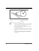
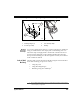
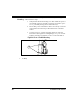
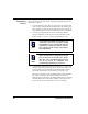
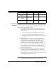
Table Of Contents
- Introduction
- Quick Start Instructions
- Using the PowerScan RF System
- Mounting the Base Station
- RF Programmable Features
- Programming Overview
- What Is Programming Mode?
- The Programming Session
- Programming Sequence
- Scanner vs. Base Station Features
- Interface (I/F) Selection
- Universal Keyboard Wedge I/F Selection
- Terminal/ Keyboard Settings
- RF Beeper Settings
- RF When to Beep
- RF When to Beep Options (continued)
- Radio Transmit Power
- RF Channel Selection
- Transmission Retries Before Message Time- out
- Wait Time for ACK
- Wait Time For Scanner Power Shutdown
- Wait Time Between Retries of Failed Transmission
- HACK Transmit Options
- Wait Time For HACK From Host
- Drop Links on Reset Option
- Drop Oldest Links Option
- Common Configuration
- Set Maximum Linked Scanners
- Source-Radio Identification (ID)
- Low Battery LED Indication
- Maintenance and Troubleshooting
- Standard Warranty
- Sample Bar Codes
- Number Pad

28 PowerScan™ RF Scanner
Figure 14. Mounting Using Key Slots
Using
Mounting
Flanges
Refer to Figure 15a and follow these steps:
1. Once you have identified the desired area for permanent Base
Station installation, hold the unit in place and mark the posi-
tion of screws using the "mounting flanges."
2. Start and remove four screws (provided) at the marked posi-
tions in the mounting surface.
3. Ensure that power and interface cables are securely connected
and routed in the channels provided in the bottom of the Base
Station.
4. Secure the Base Station to the surface by installing the four
screws into the mounting flanges. Base Station attachment is
now complete.
1. Key Slots 2.
#8 x 1" (4.1mm x 25.4mm) Pan
Head Screw
BA
SE ID
T
X/RX
C
HAR
G
E
PO
W
E
R
1
2