
User's Manual
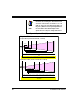
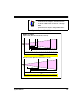
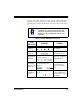
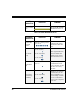
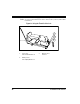
Table Of Contents
- Introduction
- Quick Start Instructions
- Using the PowerScan RF System
- Mounting the Base Station
- RF Programmable Features
- Programming Overview
- What Is Programming Mode?
- The Programming Session
- Programming Sequence
- Scanner vs. Base Station Features
- Interface (I/F) Selection
- Universal Keyboard Wedge I/F Selection
- Terminal/ Keyboard Settings
- RF Beeper Settings
- RF When to Beep
- RF When to Beep Options (continued)
- Radio Transmit Power
- RF Channel Selection
- Transmission Retries Before Message Time- out
- Wait Time for ACK
- Wait Time For Scanner Power Shutdown
- Wait Time Between Retries of Failed Transmission
- HACK Transmit Options
- Wait Time For HACK From Host
- Drop Links on Reset Option
- Drop Oldest Links Option
- Common Configuration
- Set Maximum Linked Scanners
- Source-Radio Identification (ID)
- Low Battery LED Indication
- Maintenance and Troubleshooting
- Standard Warranty
- Sample Bar Codes
- Number Pad

Systems Manual 19
Figure 12. Depth of Field (XLR)
NOTE
See the section titled, Definition of a "mil" for more
information about reading this chart. Measurements
are based on XLR models set with a 10° scan angle
width.
Specifications are subject to change without notice.
Depth of Field
Paper Labels (XLR decoded model, Code 39)
0
40 mil
20 mil
15 mil
CENTIMETERS
FEET
FRONT OF SCANNER
12345678910 11 12 13 14 15
45040035030025020015010050
55 mil
Reflective Labels (XLR decoded model, Code 39)
70 mil
40 mil
CENTIMETERS
FEET
FRONT OF SCANNER
11001050100095090085080075070065060055050045040035030025020015010050
1
0
2345678910 11 12 13 14 15 16 17 18 19 20 21 22 23 24 25 26 27 28 29 30 31 32 33 34 35 36
100 mil