
User's Manual
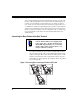
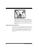
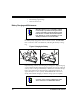
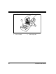
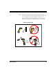
Table Of Contents
- Introduction
- Quick Start Instructions
- Using the PowerScan RF System
- Mounting the Base Station
- RF Programmable Features
- Programming Overview
- What Is Programming Mode?
- The Programming Session
- Programming Sequence
- Scanner vs. Base Station Features
- Interface (I/F) Selection
- Universal Keyboard Wedge I/F Selection
- Terminal/ Keyboard Settings
- RF Beeper Settings
- RF When to Beep
- RF When to Beep Options (continued)
- Radio Transmit Power
- RF Channel Selection
- Transmission Retries Before Message Time- out
- Wait Time for ACK
- Wait Time For Scanner Power Shutdown
- Wait Time Between Retries of Failed Transmission
- HACK Transmit Options
- Wait Time For HACK From Host
- Drop Links on Reset Option
- Drop Oldest Links Option
- Common Configuration
- Set Maximum Linked Scanners
- Source-Radio Identification (ID)
- Low Battery LED Indication
- Maintenance and Troubleshooting
- Standard Warranty
- Sample Bar Codes
- Number Pad

10 PowerScan™ RF Scanner
Figure 5. Connecting Power to the Base Station
5. Apply power to the Host Terminal.
6. Verify communication with the Host Terminal by aiming the
linked scanner at a sample bar code from Appendix A, and
pulling the trigger (see How to Scan for tips about scanning bar
codes). Confirm that the scanner/Base Station sent the data to
the host terminal. If not, see the section, Maintenance and Trou-
bleshooting. Once all communications are verified, the system is
ready for use.
Linking the Scanner to a Base Station
To link a scanner to a Base Station, simply scan the Base Station ID bar
code located on the top of the desired Base Station (see Figure 2). As the
scanner searches for the Base Station, a short beep is heard as it seeks
for the correct channel. When the Base Station responds to the request,
the scanner’s beeper will either sound a "Link Granted," or "Link
Denied" signal (see the section, LED and Beeper Indications for more
information).