
User's Manual
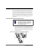
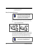
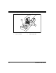
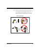
Table Of Contents
- Introduction
- Quick Start Instructions
- Using the PowerScan RF System
- Mounting the Base Station
- RF Programmable Features
- Programming Overview
- What Is Programming Mode?
- The Programming Session
- Programming Sequence
- Scanner vs. Base Station Features
- Interface (I/F) Selection
- Universal Keyboard Wedge I/F Selection
- Terminal/ Keyboard Settings
- RF Beeper Settings
- RF When to Beep
- RF When to Beep Options (continued)
- Radio Transmit Power
- RF Channel Selection
- Transmission Retries Before Message Time- out
- Wait Time for ACK
- Wait Time For Scanner Power Shutdown
- Wait Time Between Retries of Failed Transmission
- HACK Transmit Options
- Wait Time For HACK From Host
- Drop Links on Reset Option
- Drop Oldest Links Option
- Common Configuration
- Set Maximum Linked Scanners
- Source-Radio Identification (ID)
- Low Battery LED Indication
- Maintenance and Troubleshooting
- Standard Warranty
- Sample Bar Codes
- Number Pad

8 PowerScan™ RF Scanner
Verifying Scanner Operation
Once a charged battery has been installed in the scanner, scan the sam-
ple bar codes in Appendix A that correspond to the symbologies your
scanner is programmed to read. If unsure how to do this, see the sec-
tion on How to Scan in this manual. The system may signal with one or
a combination of indicators depending upon how the scanner and Base
Station are programmed to respond (see LED and Beeper Indications for
details). If your scanner fails to read a sample bar code of a symbology
it’s programmed to read, turn to the section titled, Maintenance and
Troubleshooting.
Connecting the Base Station to the Host Terminal
1. Connect the I/F cable to the Base Station (see Figure 4A). The
I/F cable is inserted into the connector and the cable retainer
clip is rotated over the cable overmold until the retainer snaps
in place (see Figure 4B). To disconnect the cable, push in on the
retainer (away from the catch on the plastic wall) to release it
and enable it to swing upward, allowing the cable to be pulled
free (see Figure 4C).
Figure 4. Connecting/Disconnecting the Interface (I/F) Cable
NOTE
It is important that the interface (I/F) cable be con-
nected to the Base Station prior to applying power
to the system. This is because the interface type
(RS-232, IBM, Keyboard Wedge, etc.) is selected by
the Base Station subject to the I/F cable it is con-
nected to at the time of power-up.
ab
c