
User Manual
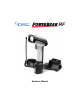
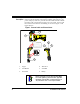
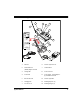

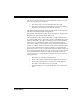
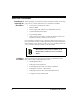
Table Of Contents
- Introduction
- Quick Start Instructions
- Using the PowerScan RF System
- Mounting the Base Station
- RF Programmable Features
- Programming Overview
- What Is Programming Mode?
- The Programming Session
- Programming Sequence
- Scanner vs. Base Station Features
- Interface (I/F) Selection
- Universal Keyboard Wedge I/F Selection
- Terminal/ Keyboard Settings
- RF Beeper Settings
- RF When to Beep
- RF When to Beep Options (continued)
- Radio Transmit Power
- RF Channel Selection
- Transmission Retries Before Message Time- out
- Wait Time for ACK
- Wait Time For Scanner Power Shutdown
- Wait Time Between Retries of Failed Transmission
- HACK Transmit Options
- Wait Time For HACK From Host
- Drop Links on Reset Option
- Drop Oldest Links Option
- Common Configuration
- Set Maximum Linked Scanners
- Source-Radio Identification (ID)
- Low Battery LED Indication
- Maintenance and Troubleshooting
- Standard Warranty
- Sample Bar Codes
- Number Pad

Systems Manual 3
Figure 2. Base Station Labels and Nomenclature
1. Antenna 8. Interface (I/F) Connector
2. Transmit/Receive
(TX/RX)/ Diagnostics LED
9. Cable Retainer
3. Charge LED 10 Power Connector
4. Power LED 11. Power Supply - (a) AC Adapter or
(b) Forklift DC Converter
5. Base ID Bar Code 12. Interface (I/F) Cable
6. Charging Pins 13. Mounting Key Slots (3)
7. 3-Position Lock 14. Mounting Flanges (4)
BASE ID
TX/RX
CHARGE
POWER
1
2
3
4
5
6
7
13
8
9
10
14
12
11
a
b
PSC
INC.
959 Terry Street
Eugene, OR 97402 U.S.A.
MODEL: PowerScan RF Base Station
CLASS No.
SERIAL No.
FREQ:
ACN
N263
Use ONLY PSC
AC/DC Power Supply
Input: +6.5V to +14V
Power: 13.9 Watts (max)
CUS
LISTED
NWGQ 2Z78
FCC ID: O9NPWRSCAN-BS
CanadaXXXXXXXXX
This device complies with Part 15 of the FCC Rules.
Operation is subject to the following two conditions:
1. This device may not cause harmful interference.
2. This device must accept any interference, including
interference that may cause undesired operation.
Applicable patents are listed on label inside handheld unit.