
User Manual
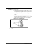
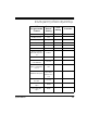
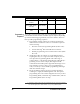
Table Of Contents
- Introduction
- Quick Start Instructions
- Using the PowerScan RF System
- Mounting the Base Station
- RF Programmable Features
- Programming Overview
- What Is Programming Mode?
- The Programming Session
- Programming Sequence
- Scanner vs. Base Station Features
- Interface (I/F) Selection
- Universal Keyboard Wedge I/F Selection
- Terminal/ Keyboard Settings
- RF Beeper Settings
- RF When to Beep
- RF When to Beep Options (continued)
- Radio Transmit Power
- RF Channel Selection
- Transmission Retries Before Message Time- out
- Wait Time for ACK
- Wait Time For Scanner Power Shutdown
- Wait Time Between Retries of Failed Transmission
- HACK Transmit Options
- Wait Time For HACK From Host
- Drop Links on Reset Option
- Drop Oldest Links Option
- Common Configuration
- Set Maximum Linked Scanners
- Source-Radio Identification (ID)
- Low Battery LED Indication
- Maintenance and Troubleshooting
- Standard Warranty
- Sample Bar Codes
- Number Pad

36 PowerScan™ RF Scanner
Programming
Sequence
To modify a scanner feature (item), the programming bar codes con-
tained in this manual must be scanned in a given sequence depending
upon the feature being programmed (as shown in Table 5). There are
three possible programming sequences:
A. Programming sample A (the most commonly used format)
demonstrates how three bar codes are scanned in sequence to
do the following:
1. Place the scanner in Programming Mode (SET bar code).
2. Scan the Item Tag
1
that will enable the new feature.
3. End the programming session and reset the scanner (END
bar code).
B. Sample B provides an example of a programming feature
requiring the entry of a range value. Like sample A, the scan-
ner is placed in Programming Mode and an Item Tag
1
is
scanned. Then, a value must be entered before ending the pro-
gramming session. In the example, three digits must be
scanned from the number pad in Appendix B. This type of for-
mat, requiring a total of as many as six programming bar
codes, is necessary to allow flexible programming with larger
item value numeric ranges.
C. The programming sequence shown in example C requires
scanning of a single, extended length bar code. This special
programming bar code contains all the data necessary to enter
Programming Mode, set the Item Tag
1
and Item Value, and exit
Programming Mode (all in one step).
Common Configuration Disable
Set Maximum Linked
Scanners
8
Source-Radio Identifi-
cation (ID)
Don’t Include
Low Battery LED Indi-
cation
Enable
1. An “Item Tag” is a term used to describe an assigned number, which is encoded in a programming
bar code, that toggles (selects, enables, disables, etc.) a specific programming feature.