
User Manual
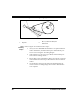
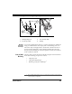
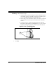
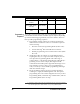
Table Of Contents
- Introduction
- Quick Start Instructions
- Using the PowerScan RF System
- Mounting the Base Station
- RF Programmable Features
- Programming Overview
- What Is Programming Mode?
- The Programming Session
- Programming Sequence
- Scanner vs. Base Station Features
- Interface (I/F) Selection
- Universal Keyboard Wedge I/F Selection
- Terminal/ Keyboard Settings
- RF Beeper Settings
- RF When to Beep
- RF When to Beep Options (continued)
- Radio Transmit Power
- RF Channel Selection
- Transmission Retries Before Message Time- out
- Wait Time for ACK
- Wait Time For Scanner Power Shutdown
- Wait Time Between Retries of Failed Transmission
- HACK Transmit Options
- Wait Time For HACK From Host
- Drop Links on Reset Option
- Drop Oldest Links Option
- Common Configuration
- Set Maximum Linked Scanners
- Source-Radio Identification (ID)
- Low Battery LED Indication
- Maintenance and Troubleshooting
- Standard Warranty
- Sample Bar Codes
- Number Pad

30 PowerScan™ RF Scanner
Post or Forklift
Mounting
To secure the Base Station to a post or forklift frame, refer to Figure 16
and follow these steps:
1. Verify that the desired mounting area offers sufficient space for
safe forklift operation and will not present a hazard for opera-
tors or potentially damage the mounted device(s).
2. Ensure that power and interface cables are securely connected
and routed in the channels provided in the back of the Base
Station.
3. Using tie-wraps or a similar strapping material, secure the
Base Station (through the mounting flanges) to a post or frame.
Tighten and adjust as needed to assure a secure installation.
Figure 16. Post or Forklift Mounting
1. Tie Wraps
1