
User Manual
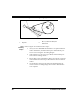
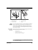
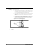
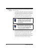
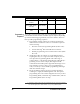
Table Of Contents
- Introduction
- Quick Start Instructions
- Using the PowerScan RF System
- Mounting the Base Station
- RF Programmable Features
- Programming Overview
- What Is Programming Mode?
- The Programming Session
- Programming Sequence
- Scanner vs. Base Station Features
- Interface (I/F) Selection
- Universal Keyboard Wedge I/F Selection
- Terminal/ Keyboard Settings
- RF Beeper Settings
- RF When to Beep
- RF When to Beep Options (continued)
- Radio Transmit Power
- RF Channel Selection
- Transmission Retries Before Message Time- out
- Wait Time for ACK
- Wait Time For Scanner Power Shutdown
- Wait Time Between Retries of Failed Transmission
- HACK Transmit Options
- Wait Time For HACK From Host
- Drop Links on Reset Option
- Drop Oldest Links Option
- Common Configuration
- Set Maximum Linked Scanners
- Source-Radio Identification (ID)
- Low Battery LED Indication
- Maintenance and Troubleshooting
- Standard Warranty
- Sample Bar Codes
- Number Pad

Systems Manual 29
Figure 15. Mounting Using Flanges or Two-sided Tape
Mounting
Using Two-
Sided Tape
You can also affix the Base Station to a surface using the two-sided tape
strips provided with the unit. Simply remove the backing from one
side of the strips and apply them to the bottom of the Base Station as
shown in Figure 15b. Remove the remaining backing from the tape,
then position and firmly press the unit against a smooth, clean surface
in the orientation desired.
Vertical (Wall)
Mounting
The Base Station can be mounted vertically using the same methods as
horizontal mounting (see previous section):
• Using Key Slots
• Using Mounting Flanges
• Mounting Using Two-Sided Tape
1
1. Mounting Flanges (4) 3. Two-sided Tape Strips
2. 4 Screws (provided) 4. Backing
BASE ID
TX/RX
CHARGE
POWER
1
2
3
4
ab
1. Since mounting using this method offers less secure attachment, verify that your tape installation
is robust enough for your application.