
User Manual
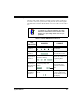
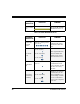
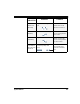
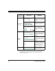
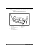
Table Of Contents
- Introduction
- Quick Start Instructions
- Using the PowerScan RF System
- Mounting the Base Station
- RF Programmable Features
- Programming Overview
- What Is Programming Mode?
- The Programming Session
- Programming Sequence
- Scanner vs. Base Station Features
- Interface (I/F) Selection
- Universal Keyboard Wedge I/F Selection
- Terminal/ Keyboard Settings
- RF Beeper Settings
- RF When to Beep
- RF When to Beep Options (continued)
- Radio Transmit Power
- RF Channel Selection
- Transmission Retries Before Message Time- out
- Wait Time for ACK
- Wait Time For Scanner Power Shutdown
- Wait Time Between Retries of Failed Transmission
- HACK Transmit Options
- Wait Time For HACK From Host
- Drop Links on Reset Option
- Drop Oldest Links Option
- Common Configuration
- Set Maximum Linked Scanners
- Source-Radio Identification (ID)
- Low Battery LED Indication
- Maintenance and Troubleshooting
- Standard Warranty
- Sample Bar Codes
- Number Pad

24 PowerScan™ RF Scanner
Table 4. Base Station LED Functions
LED
INDICATION
DURATION COMMENT
TX/RX (Trans-
mit/Receive)
Lit for variable time
a
a. The LED remains on while the unit is actively processing code which
requires a TX/RX to occur. The duration of the LED is dependent upon
the length of the message.
Indicates communications
activity to or from the Base
Station.
Continuous rapid
flashing at power-up
Indicates a broken radio.
Varies. Consists of a long flash
followed by multiple short
flashes.
Enables service techni-
cians to identify Field
Replaceable Unit (FRU)
errors.
Charge
(Battery)
Continuous flashing
When a scanner is nested
in the station, this indicates
its battery is being quick
charged.
Lit Constantly
When a scanner is nested
in the station, this indicates
its battery is at or near full
charge.
Not Lit
A scanner is not present or
incorrectly inserted into the
station. It can also mean
the battery is below 0°C
(too cold for charge)
Power
Lit Constantly
Indicates that power is on.