
User Manual
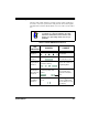
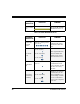
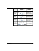
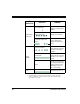
Table Of Contents
- Introduction
- Quick Start Instructions
- Using the PowerScan RF System
- Mounting the Base Station
- RF Programmable Features
- Programming Overview
- What Is Programming Mode?
- The Programming Session
- Programming Sequence
- Scanner vs. Base Station Features
- Interface (I/F) Selection
- Universal Keyboard Wedge I/F Selection
- Terminal/ Keyboard Settings
- RF Beeper Settings
- RF When to Beep
- RF When to Beep Options (continued)
- Radio Transmit Power
- RF Channel Selection
- Transmission Retries Before Message Time- out
- Wait Time for ACK
- Wait Time For Scanner Power Shutdown
- Wait Time Between Retries of Failed Transmission
- HACK Transmit Options
- Wait Time For HACK From Host
- Drop Links on Reset Option
- Drop Oldest Links Option
- Common Configuration
- Set Maximum Linked Scanners
- Source-Radio Identification (ID)
- Low Battery LED Indication
- Maintenance and Troubleshooting
- Standard Warranty
- Sample Bar Codes
- Number Pad

22 PowerScan™ RF Scanner
Table 2. Scanner YELLOW LED Functions
Table 3. Scanner BEEPER Functions
LED
INDICATION
DURATION COMMENT
Laser on indica-
tion
On Steady
The yellow LED illuminates
whenever the laser is on.
SPEAKER
INDICATION
DURATION COMMENT
Scanner Not
Currently
Linked
Six beeps consisting of 20 ms
on, 20 ms off
Indicates a bar code was
read before the scanner
was linked to a Base Sta-
tion.
Good Read
Beep
100 ms on (short)
250 ms on (medium)
500 ms on (long)
Three programmable func-
tions are available. This
indicates a bar code has
been read and decoded.
Partial Read
Bip
20 ms on
A very short beep ("bip") is
sounded when one bar
code of a two-bar code pair
has been successfully
decoded.
Base Station
Acknowledge-
ment Beep
100 ms on (short)
250 ms on (medium)
500 ms on (long)
Indicates a successful bar
code transmission to the
host (configurable), a suc-
cessful change of channel,
or a successful transmis-
sion of a new configuration
to the host.