
User Manual
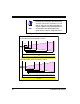
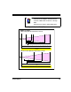
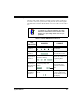
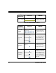
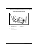
Table Of Contents
- Introduction
- Quick Start Instructions
- Using the PowerScan RF System
- Mounting the Base Station
- RF Programmable Features
- Programming Overview
- What Is Programming Mode?
- The Programming Session
- Programming Sequence
- Scanner vs. Base Station Features
- Interface (I/F) Selection
- Universal Keyboard Wedge I/F Selection
- Terminal/ Keyboard Settings
- RF Beeper Settings
- RF When to Beep
- RF When to Beep Options (continued)
- Radio Transmit Power
- RF Channel Selection
- Transmission Retries Before Message Time- out
- Wait Time for ACK
- Wait Time For Scanner Power Shutdown
- Wait Time Between Retries of Failed Transmission
- HACK Transmit Options
- Wait Time For HACK From Host
- Drop Links on Reset Option
- Drop Oldest Links Option
- Common Configuration
- Set Maximum Linked Scanners
- Source-Radio Identification (ID)
- Low Battery LED Indication
- Maintenance and Troubleshooting
- Standard Warranty
- Sample Bar Codes
- Number Pad

18 PowerScan™ RF Scanner
Figure 11. Depth of Field (LR)
NOTE
See the section titled, Definition of a "mil" for more
information about reading this chart. Measurements
are based on LR models set with the a 14° scan
width (as opposed to the alternate Full Angle set-
ting of 28°). Reference the Programming Manual for
more information about the Half Angle feature.
Specifications are subject to change without notice.
Depth of Field
Paper Labels (LR decoded model, Code 39)
0
40 mil
20 mil
15 mil
7.5 mil
CENTIMETERS
FEET
FRONT OF SCANNER
10
12345
20 30 40 50 60 70 80 90 100 110 120 130 140 150 160
6789
170 180 190 200 210 220 230 240 250 260 270 280
10 mil
55 mil
Reflective Labels (LR decoded model, Code 39)
70 mil
55 mil
40 mil
CENTIMETERS
FEET
FRONT OF SCANNER
6706506306105905705505305104904704504304103903703503303102902702502302101901701501301109070503010
1
0
2345678910 11 12 13 14 15 16 17 18 19 20 21 22
100 mil