
User's Manual

Datalogic Scanning, Inc
959 Terry Street
Eugene, Oregon 97402
Page 14 10/23/2009
Revision X2
directly.
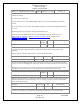
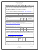
For example, power_setting { 0x0d11, 0, 0x3f11, 0x4d00, 0xf800 } specifies:
To get power output -8 dBm for basic data rate (1 Mbps) use
internal amp 13, external amp 17.
To get power output -8 dBm, for enhanced data rate (2 or 3 Mbps) use
internal amp 63, external amp 17, TX-PRE amp 0x4d.
A power table is a list of these entries. The entries must be in ascending order of transmit power.
If the table contains only one entry (five uint16s) then the firmware always uses these settings.
The firmware responds to peer requests to increase/decrease transmit power by stepping up and down this
table. The Bluetooth spec. constrains the sizes and number of steps, which in turn bounds the size and
content of the power table.
In EDR operation, if the bottom bit of the fourth word is set, the power is marked as unavailable for EDR
transmissions. Depending on the setting of BCCMD Limit_EDR_Power, the chip will either change the
packet type table to basic rate; or refuse peer power control requests which request it to exceed the
maximum allowed EDR power. If PSKEY_LC_DEFAULT_TX_POWER
is greater than the maximum
allowed EDR power, BlueCore will refuse to enter use EDR until the peer requests it to decrement its
power sufficiently, after which it will attempt to change the packet type table to use EDR.
Note that, although this table is not used directly for the CSR-specific radiotest command set, two features
of this table are used to determine transmitter behaviour in radiotest mode:
- The first entry in the table is used to determine the fixed
internal_pa setting for EDR operation. The internal_pa
value passed to the radiotest command in EDR mode (indicated
by packet types of 16 or over) is used to control the TX-PRE
level in the manner described above.
- The presence of an entry with the `EXT PA' bit set is
necessary before radiotest will use the class1 logic to
transmit. However, in addition, the external_pa value
passed to radiotest (the upper byte of the transmitter gain)
must be non-zero for class 1 mode to be used.
See PSKEY_TXRX_PIO_CONTROL
to see how the chip's AUX_DAC pin controls an external PA.
The current Casira design has a fixed-gain external PA; its AUX_DAC is not connected to the PA. The
default power table thus always has external_pa set to zero.
See PSKEY_LC_POWER_TABLE, PSKEY_LC_MAX_TX_POWER
,
PSKEY_LC_DEFAULT_TX_POWER
, PSKEY_LOCAL_SUPPORTED_FEATURES,
PSKEY_TXRX_PIO_CONTROL
, PSKEY_TX_AVOID_PA_CLASS1_PIO,
PSKEY_TRANSMIT_OFFSET_CLASS1, PSKEY_TX_PRE_LVL_CLASS1
,
PSKEY_TRANSMIT_OFFSET_HALF_MHZ, PSKEY_TRANSMIT_OFFSET
, and
PSKEY_TX_PRE_LVL
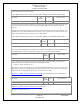
Key Name Key
Number
Type Default Setting