
Specifications
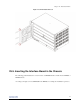

Chapter 25. Installation Guide
WARNING:
"Consult the table about the type of fuse used in each interface module. If necessary, replace it only for
another one of the same type and value."
25.2.1. Cables
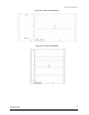
Table 25-1. Cable dimension according chassis
Chassis Current max. Minimum conductor sizes
Nominal cross-sectional area AWG [cross-sectional area in mm2]
DM4001 2,5A 1,5mm2 14 [2 mm2]
DM4004 12,5A 2,5mm2 12 [3 mm2]
DM4008 22A 4mm2 10 [5 mm2]
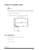
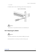
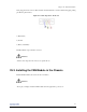
25.2.1.1. Build Information from DM4001 power connector and
DM4004/DM4008 power connector
To connect the equipment, you should connect power supply to D-metro connector type 3W3 (-48/-60Vdc,
Ground, Return - 0V), DC input (-48/-60Vdc).
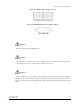
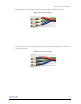
Are necessary the follow itens to build the power supply cable, according chassis cable dimensions:
• 2 mm2, 3 mm2 or 5 mm2 section area cable - Red (Return)
• 2 mm2, 3 mm2 or 5 mm2 section area cable - Blue (-48/-60Vdc)
• 2 mm2, 3 mm2 or 5 mm2 section area cable - Green with Yellow Stripes (Ground)
• Thermocontractile Tube 4,8/2,4mm
• Connector cape DB3W3*
• Female connector DB3W3 without pins*
• Female connector DB Pin Power 40A (3 pins per connector)*
*These itens are provided by DATACOM with the equipment
94