
User guide


Hardware 19
© 2012 Datacom Systems Inc
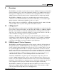
3.4 Front Panel Description
This section provides a illustration and description of the front panel of the SS-1200-S, SS-2200-S
and SS-4200-S series.
An explanation of each front panel legend follows:
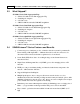
3.4.1 Power
Two switching AC adapter power supplies are provided for each configurable unit. Although only
one power supply is required to power the module, use of a second independent power source is
strongly recommended to assure uninterrupted monitoring. Furthermore, connecting the second AC
input power socket to a different external power source circuit than the first AC input power source
eliminates power as a single point of failure. The power barrel sockets are located on the rear.
The POWER 1 and 2 front panel LEDs illuminate green when power is available at
both of the two rear power barrel sockets indicating power 1 and 2, respectively, are
on. Either LED not illuminated indicates a defective power source and immediate
investigation as to the cause is required to insure redundant power integrity.
3.4.2 TAP Ports
BT - TAP
BT - TAP (SS-1204BT-S port 1 and port 2) or TAP 1 and TAP 2 (SS-2206BT-S port 1 and port
2; port 3 and port 4) or TAP 1, TAP 2, TAP 3, and TAP 4 (SS-4210BT-S port 1 and port 2; port 3
and port 4; port 5 and port 6; port 7 and port 8) are RJ45 connectors used for connection to
network segments. These jacks have integrated LEDs that display line status and line speed of each
port. See the TAP LED Display Code table for LED display codes.
IMPORTANT: All BT taps can be configured to have traffic, for example TCP resets, injected from
Any-to-Any ports.