AM100 SECURITY SYSTEM INSTALLATION INSTRUCTIONS N7526-3V1 Rev B 4/99 Ref: 20AMTE
RECOMMENDATIONS FOR PROPER PROTECTION The Following Recommendations For The Location Of Fire And Burglary Detection Devices Help Provide Proper Coverage For The Protected Premises. Recommendations For Smoke And Heat Detectors With regard to the number and placement of smoke/heat detectors, we subscribe to the recommendations contained in the National Fire Protection Association's (NFPA) Standard #72 noted below.
TABLE OF CONTENTS Section 1. GENERAL DESCRIPTION .................................................................................................. . 7 Section 2. INSTALLING THE CONTROL............................................................................................ . 10 Mounting the Cabinet ....................................................................................................... . 10 Installing the Lock (if used) ..................................................................
Section 8. 4285 & 4286VIP PHONE MODULES ................................................................................ .32 Installing the Phone Module............................................................................................. . 32 General Information ....................................................................................................... . 32 Mounting The Phone Module ........................................................................................ .
Remote Programming Information................................................................................... . 79 Remote Programming Advisory Notes .............................................................................. 79 Section 23. SYSTEM COMMUNICATION ............................................................................................ . 80 Report Code Formats......................................................................................................... .
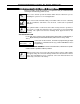
CONVENTIONS USED IN THIS MANUAL MAIN SECTION TITLES ARE SHOWN IN REVERSE TYPE Before you begin using this manual, it is important that you understand the meaning of the following symbols (icons). UL These notes include specific information which must be followed if you are installing this system for a UL Listed application. These notes include information that you should be aware of before continuing with the installation, and which, if not observed, could result in operational difficulties.
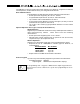
Section 1. GENERAL DESCRIPTION The AM100 is a security system control that supports up to 38 zones, using basic hard-wired, wired expansion, and/or wireless zones, plus 3 keypad activated zones. Basic Hardwired Zones Provides 8 basic hardwired zones having the following characteristics: • EOLR supervision supporting N.O. or N.C.
Security Codes • • • • • One installer code for entire system (user 1) One Master code for entire system (user 2) 12 secondary user codes (users 3–14) One baby-sitter code (user 15) One duress code (user 16) Baby-sitter Code: A special code that can only be used to disarm the system if that particular code (or the installer code) was used to arm it. Duress Code: An emergency code which, when entered by any user to disarm or arm the system, will send a silent duress message to the central station.
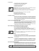
Optional Long Range Radio • Allows all messages that have been programmed to go to the primary telephone number to be reported additionally to a 7720PLUS or 7820 radio. Check availability of these models. Built-in Telephone Line Monitoring Option • The telephone line voltage can be monitored to supervise the phone line connection. The panel must be connected to a proper earth ground or you will get a false line cut indication if this feature is enabled.
Section 2. INSTALLING THE CONTROL This section provides instructions for mounting the control cabinet and installing the cabinet lock (if used).
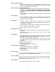
Mounting The Control's Circuit Board Alone in The Cabinet (Fig. 2) 1. Hang two short Black mounting clips (provided) on the raised cabinet tabs (see Detail B in Fig. 2). 2. Insert the top of the circuit board into the slots at the top of the cabinet. Make sure that the board rests on the correct row (see Detail A ). 3. Swing the base of the board into the mounting clips and secure the board to the cabinet with the accompanying screws (see Detail B in Fig. 2). Figure 2.
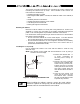
Standard Phone Line Connections The wiring connections shown here are not applicable if the 4285/4286 Phone Module is used. Refer to the 4285/4286 Phone Module section for information regarding phone line connections, which are different than those shown here.
b. Wire the other three terminals (Sync, Data, Com) on the 4300 transformer. Wires from these terminals must be connected to a 9-pin connector on the control board (using a 4142TR cable supplied with the 4300 transformer), as shown in Figure 5. These particular wires can be 24 gauge or larger, and can be run along with the AC and ground wires to the control panel.
Section 3. INSTALLING REMOTE KEYPADS This section lists the wired keypads that may be used and provides instructions for wiring and mounting the keypads. A preliminary check-out procedure is also provided to ensure that the connected keypads are functioning properly in the system.
4 BLACK RED 5 6 GREEN KEYPAD YELLOW 7 CONTROL TERMINALS Figure 6. Keypad Connections To The Control Board Mounting the Keypads 1. Make sure addressable type keypads (AM6128 and AM6139) are set to non-addressable mode (address 31), which is the factory default setting. Refer to the instructions provided with the keypad for address setting procedure. 2. Mount the keypads at a height that is convenient for the user. Refer to the instructions provided with the keypad for mounting procedure.
SUPPLEMENTARY POWER SUPPLY + CONTROL TERMINAL STRIP – TO KEYPAD YEL WIRE TO KEYPAD GRN WIRE TO KEYPAD BLK WIRE IMPORTANT: MAKE THESE CONNECTIONS DIRECTLY TO SCREW TERMINALS AS SHOWN. TO KEYPAD RED WIRE TO KEYPAD YEL WIRE TO KEYPAD GRN WIRE TO KEYPAD BLK WIRE TO KEYPAD RED WIRE AUX AUX. DATA DATA – + IN OUT 4 5 6 7 Figure 7.
Section 4. BASIC HARD-WIRED ZONES 1–8 This section provides general information for the hard-wired zones in the system, plus specific instructions for installing 2-wire smoke detectors, 4-wire smoke/combustion detectors, and 2-wire latching type glass break detectors.
Turning Off Fire Alarm Sounding You can turn off Fire alarm sounding by pressing the OFF key on any keypad or other arming/disarming device. To clear the "memory of alarm" and to reset the detector’s alarm, enter the security code plus OFF again. COMPATIBLE 2-WIRE SMOKE DETECTORS Detector Type Photoelectric w/heat sensor, direct wire Photoelectric, direct wire Photoelectric w/heat sensor, direct wire Photoelectric Photoelectric w/heat sensor Ionization, direct wire System Sensor Model No.
COMPATIBLE 4-WIRE SMOKE/COMBUSTION DETECTORS 1412 System Sensor, 4-wire ionization products of combustion detector 2412 System Sensor, 4-wire photoelectric smoke detector 2412TH System Sensor, 4-wire photoelectric smoke detector w/135º F (57º C) heat detector A77–716B System Sensor, EOL relay module (supervisory module for wired 4-wire fire zone).
Programming Hard-Wired Zones Each zone must be programmed into the system using the ✱56 Zone Programming mode, which assigns characteristics that define the way the system responds to faults on that zone. Refer to the Zone Response Type section and the Zone Programming section for specific instructions on programming hard-wired zones. Check-Out Procedure For Hard-Wired Zones After installation and programming of all hard-wired devices is completed, the security system should be checked, as follows. 1.
Section 5. WIRED ZONE EXPANSION This section provides information regarding the use of expansion modules for expanding the number of wired zones in the system, the modules that can be used and their wiring connections. Installing Zone Expansion Units You can add an additional 8 wired EOLR zones to the basic control's 8 zones, for a total of 16 wired zones, by using a No. 4219 Wired Expansion Unit, or 4229 Wired Expansion/Relay Unit.
Programming Wired Expansion Zones Each zone must be programmed into the system using the ✱ 56 Zone Programming mode, which assigns characteristics that define the way the system responds to faults on that zone. Refer to the Zone Response Type section and the Zone Programming section for specific instructions on programming wired expansion zones.
Section 6. WIRELESS EXPANSION (5800 SYSTEM) This section provides instructions for installing 5800 series wireless receivers and transmitters. General Information In addition to its basic wired zones, the control supports up to 30 wireless zones using an appropriate 5881 (5882 in Canada) type RF receiver. The actual number of zones supported depends on whether you are using a wired zone expander module.
Installation and Setup of the 5881/5882 Receiver OFF 1 2 3 4 ON ON 1. 2. 3. 4. Set the receiver's DIP switch for device address “0”, as described in its instructions (all switches to the right. . . “off”). Mount the receiver. The RF receiver can detect signals from transmitters within a nominal range of 200 feet. Take this into consideration when determining mounting location. Connect the receiver's wire harness to the control's keypad terminals (4, 5, 6, and 7).
Installing the 5800TM Module Installation of this module is necessary only if you are using one or more 5827BD Wireless Bi-directional keypads or 5804BD transmitters. Mounting the 5800TM Module The 5800TM must be located next to the RF receiver (between one and two feet from the receiver’s antennas). The 5800TM must not be installed within the control cabinet. Mount the unit using its accompanying mounting bracket.
Transmitter Input Types All of the transmitters described have one or more unique factory assigned input (loop) ID codes. Each of the inputs requires its own programming zone (e.g., a 5804's four inputs require four programming zones). See APPENDIX A toward the end of this manual. Transmitters can be enrolled as one of the following types: Type Description "RF" (Supervised RF) Sends periodic check-in signals, as well as fault, restore, and low battery signals.
5800 Series Transmitters Table Also refer to APPENDIX A near end of this manual for transmitter input loops/button locations. Model Description 5801 Wireless Panic Transmitter • Unit has 4 pushbuttons, each with a unique Input (loop) code. • Each pushbutton must be assigned to a zone. Enroll as “3” for RF (supervised), or “4” for UR (unsupervised). Note: Input loop (button) No. 4 must always be used.
Installing 5800 Series Transmitters To be sure reception of the transmitter's signal at the proposed mounting location is adequate, perform a Go/No Go test. Go/No Go Test Mode The Go/No Go tests will verify adequate RF signal strength from the proposed transmitter location, and allow you to reorient or relocate transmitters if necessary, before mounting the transmitters permanently. This mode is similar to the transmitter test mode , except that the wireless receiver gain is reduced.
Section 7. RELAY OUTPUTS & POWERLINE CARRIER DEVICES Relay/Powerline Carrier Device Basics Relays and Powerline Carrier devices (ex. X-10 brand devices) are programmable switches that can be used to perform many different functions. They can be used to turn lights on and off, control sounders, or for status indications. In this system, each device must be programmed as to how to act (ACTION), when to activate (START), and when to deactivate (STOP).
➞ RELAY 2 ➞ EITHER OR BOTH CAN BE USED RELAY 1 NO C NC { RLY 1 RELAYS "OFF" 1 2 3 4 5 6 4 TB1 7 9 8 10 11 12 4 3 2 3 1 1 2 ➞ { { NO NC C GND NO NC C WHT GRY VIO BLK YEL ORG BRN TAMPER JUMPER POSITION 4229 IN CABINET (NOT TAMPERED) 4229 REMOTE (TAMPER PROTECTED) REED (TAMPER) SWITCH ➞ RLY 2 1K ZONES: A B TERMINALS ON CONTROL PANEL TB2 4-PIN CONSOLE PLUG ➞ } 4229 DIP SWITCH FOR SETTING ADDRESS AND ZONE “A” RESPONSE ➞ ➞ ▲ } ▲ RELAY CONNECTOR C D E F G GRN D
Wiring Connections 1. Splice one end of a 3-conductor cable to the wire ends of the 4142TR cable supplied with the 4300 transformer. 2. Connect the 4142TR cable plug to the 9-pin connector on the control (see SUMMARY OF CONNECTIONS diagram for location of the 9-pin connector). 3. Connect the other end of the 3-conductor cable to the 4300 transformer, as indicated in the table below and in the diagram that follows. 4300 TRANSFORMER WIRE CONNECTIONS 4300 Terminal 1 (AC) To Terminal On Control 1 (16.
Section 8. 4285 & 4286VIP PHONE MODULES This section provides instructions for mounting and wiring the 4285 or 4286 Phone Modules. Installing the Phone Module General Information The 4285 or 4286VIP Phone Modules are add-on accessories for the AM100 that permits access to the security system via a Touch-tone phone (either on premises or by a call-in when away). The 4286VIP phone module has the additional capability of controlling thermostat(s) and providing external speaker output.
Phone Module Wiring The 4285 or 4286 phone module is wired between the control panel and the premises handset(s). It listens for touch tones on the phone line and reports them to the control panel. During on-premises phone access, it powers the premises phones; during off-premises phone access, it seizes the line from the premises phones and any answering machines. Note: The phone lines must be in service for the phone module to function, even when accessing the system from an on-premises phone. 1.
4285/4286 WIRING NOTES: 1. Wire either Phone Module exactly as shown, using a direct-connect cord and RJ31X jack. 2. If Touch-tones are not heard when pressing keys following phone access to the security system via an on-premises phone, try reversing the pair of wires connected to terminals 3 & 4 on either phone module and the pair of wires connected to terminals 21 & 22 on the control. 3.
Programming the 4285/4286 Phone Module The system must be programmed for use with the 4285 or 4286 Phone Module, including assigning a phone code and selecting words from the alpha vocabulary. Refer to the Programming sections for specific programming details. Checking the Operation of the 4285/4286 Phone Module To Check Phone Module Operation From an On-Premises Phone: 1. Pick up phone and enter the programmed 2-digit phone code. Annunciation of a system status report should automatically start.
Section 9. EXTERNAL SOUNDERS This section provides a list of compatible sounders and connection information for an external sounder. Compatible Sounders Ademco AB-12M 10” Motorized Bell & Box Ademco 1011BE12M 10” Motorized Bell & Box Ademco 702 Outdoor Siren Motor bell & box. UL Grade A. 100 mA current draw. Motor bell & box. UL Listed. 100 mA current draw. Ademco 719 2-Channel Siren Two-channel, self-contained 6–12-volt siren (driver built in). 109dB @ 10 feet. 550mA current draw.
Sounder Connections The AM100 provides a 12VDC output which can power external alarm sounders (bells or sirens, see compatible sounders listed previously). This output will activate a sounder when an alarm occurs. Make connections to alarm output terminals 3 (+) and 4 (–). See Figure 17. Non-UL Installations The total current drawn from this output cannot exceed 2 amps. A battery must be installed since this current is supplied by the battery.
Section 10. LONG RANGE RADIO General Information Check availability of Models 7720 PLUS or 7820 long range radios. If output to long range radio is selected, all messages that are programmed to go to the primary telephone line receiver will also be sent to the 7720 PLUS or 7820 long range radio. These messages will be in Contact ID format (not affected by entry in field ✱48). UL For UL installations, Long Range Radio must be disabled (✱29 = “0”).
Section 11. REMOTE KEYSWITCH This section provides instructions for the connection of an optional remote 4146 keyswitch for remote arming and disarming of the system, and the programming necessary when a keyswitch is used. Also included is a description of how the keyswitch operates in the system. Installing the Keyswitch The remote 4146 keyswitch (with red and green LEDs to indicate status) is connected to zone 7. Remote Keyswitch Connections 1.
9 PIN CONNECTOR ON CONTROL BOARD BLACK BLUE BROWN GREEN RED WHITE YELLOW GRAY VIOLET 1 2 3 4 5 6 7 8 9 4142TR CABLE (ARMED) RED BLACK BROWN BLUE } THESE WIRES NOT CONNECTED IF 4300 INTERFACE TRANSFORMER IS NOT BEING USED YELLOW (READY) GREEN RED (+ AUX POWER) TO 9 PIN CONNECTOR WHITE YELLOW (NOT USED) 820Ω GREEN BLACK BLACK RED TAMPER SWITCH (N.C.
Programming For The Remote Keyswitch 1. With one 2-line Alpha keypad (AM6139), enter the programming mode by entering: Installer code + 8 + 0 + 0 keys. If RF zones, wired expansion, or a keyswitch will be used, data fields ✱22 RF SYSTEM, ✱ 25 WIRED ZONE EXPANSION and ✱30 KEYSWITCH ENABLE must be programmed as required prior to continuing. 2. Note: If keyswitch is enabled, in menu mode ✱56 the Zone Type (ZT) for zone 7 will show “77”, and will not be accessible for programming. Press ✱56.
07 Response Time 1 If keyswitch is enabled (in programming mode, field ✱30 ) , the response is preset to 350ms. Therefore no entry is required. Press [✱] to continue. Typical summary display RC In RT 3C HW: 1 A summary display will appear, showing the data for zone 07 that was just programmed. If it is programmed satisfactorily, press [✱] to continue. P r o g r a m Al p h a ? 0 = No 1 = Ye s 0 The next request is to enter an Alpha descriptor for zone 7.
Section 12. AUDIO ALARM VERIFICATION (AAV) UNIT General Information An Audio Alarm Verification (AAV) module, such as the Eagle 1241, is an add-on accessory that permits voice dialog between an operator at a central station and a person at the alarm installation, for the purpose of alarm verification.
TIP RING INCOMING TELCO LINE ▲ (TIP) RED (RING) GREY (RING) GREEN (TIP) 23 ANSWERING MACHINE 24 25 EARTH GROUND 5 6 7 8 REFER TO AAV MODULE INSTRUCTIONS FOR CONNECTIONS TO AUDIO SPEAKERS AND MICROPHONE 22 PLUG PREMISES ANSWERING MACHINE AND PHONES (RING) ▲ 21 9 10 11 12 13 14 15 16 ON ➡ TIP RJ31X JACK RING ▲ ▲ TERMINALS ON CONTROL BROWN (TIP) ➧ ▲ DIRECT CONNECT CORD 1 2 3 4 EAGLE SECURITY MODEL 1241 INPUT TRIGGER RING (TO TERM. 22 ) TIP (TO TERM.
Section 13. FINAL POWER UP This section provides information about final power-up procedures and battery size calculations. Earth Ground Connections The designated earth ground terminal (25) must be terminated in a good earth ground for the lightning transient protective devices in this product to be effective. It also must be grounded to enable the telephone line fault indicator to work properly.
Making the Battery Connections 1. Use the battery standby formula (above) to select the appropriate battery for the installation. Do not connect the battery until all devices have been wired to the control. 2. 3. Attach the Red and Black wires on the battery connector cable as follows: a) Red to the positive (+) battery tab on the control board. b) Black to the negative (–) battery tab on the control board.
Section 14. MECHANICS OF PROGRAMMING This section provides information on how to use the system's programming modes. It will enable you to understand how to enter and exit programming mode, and how to program the data fields and how to use the user-friendly interactive modes (✱56, ✱80, ✱81, ✱82, ✱83). If RF zones or wired expansion will be used, the following program fields must be programmed (as required) before doing any zone programming.
3. If the number of digits that you need to enter in a data field is less than the maximum digits available (for example, the phone number field), enter the desired data, then press [✱] and the next data field number to be programmed. 4. If you try to enter a non-existent field, the keypad will display EE or Entry Error. Simply re-enter [✱] plus a valid field number. Reviewing a Data Field/Erasing an Entry in a Data Field Press [#] plus Field No. Data will be displayed for that field number.
Section 15. ZONE RESPONSE TYPE DEFINITIONS General Information You must assign a zone type to each zone, which defines the way in which the system responds to faults in that zone. Zone types are defined below. Type 00 Zone Not Used Type 01 Entry/Exit Burglary #11 Program a zone with this zone type if the zone is not used. This zone type provides exit and entry delays whenever the zone is faulted if the control is armed in the AWAY or HOME modes.
Type 06 24-hour Silent Alarm This zone type sends a report to the Central Station but provides no keypad display or sounding. This zone type is usually assigned to a zone containing an Emergency button. Type 07 24-hour Audible Alarm This zone type sends a report to the Central Station, and provides an alarm sound at the keypad, and an audible external alarm. This zone type is usually assigned to a zone that has an Emergency button.
Section 16. DATA FIELD DESCRIPTIONS Descriptions of System Data Fields THE BLANK PROGRAMMING FORM SHOULD BE USED TO RECORD THE DATA FOR THIS INSTALLATION Defaults (where applicable) Are Indicated In Text The following pages list all data fields used in this control (in numerical order).
✱27 POWERLINE CARRIER DEVICE (X-10) HOUSE ID 0 Powerline Carrier devices require a House ID. This field identifies this House ID to the control. If Powerline Carrier devices are used, they are selected in field ✱ 80. House ID is entered in following manner: 0 = A, 1 = B, 2 =C, 3 = D, 4 = E, 5 = F, 6 = G, 7 = H, 8 = I, 9 = J, # + 10 = K, # + 11 = L, # + 12 = M, # + 13 = N, # + 14 = O, # + 15 = P.
✱33 ✱34 ✱35 ALARM BELL TIMEOUT 1 0 = No timeout 1 = 4 min 2 = 8 min 3 = 12 min 4 = 16 min This field determines whether the external sounder will shut off after time allotted, or continue until manually turned off.
DIALER ✱40 PROGRAMMING( ✱40 – ✱44 and ✱47 – ✱50) Fields ✱40, ✱41, ✱42: Enter up to the number of digits shown. Do not fill unused spaces. Enter 0–9, # + 11 for ✱ # + 12 for # # + 13 for a pause (2 seconds) For Fields ✱43 and ✱44: Enter digits 0–9; # +11=B; # +12=C; # +13=D; # +14=E; or # +15=F. Enter [ ✱] as the fourth digit if a 3-digit account number (for 3+1 dialer reporting format) is used. Enter 0 as the first digit of a 4digit account number for Nos. 0000–0999.
✱49 0 SPLIT/DUAL REPORTING Use options 0 - 5 when reporting to standard telephone receivers TO PRIMARY TO SECONDAR Y 0= All reports none, unless primary fails, then all 1= Alarms, Restore, Cancel Others 2= All except Open/Close, Test Open/Close, Test 3= Alarms, Restore, Cancel All 4= All except Open/Close, Test All 5= All reports All Use options 6 - 9 when reporting to a pager is desired TO PRIMARY TO PAGING No.
✱50 15-SECOND DIALER DELAY (BURGLARY) 1 0 = no dialer delay 1 = provide 15-second delay of burglary alarm report (except zone type 24) to the central station, which allows time for the subscriber to avoid a false alarm transmission. This delay does not apply to zone type 24 alarms, which are always sent as soon as they occur.
SYSTEM STATUS REPORT CODES (✱59 – ✱68) ✱59 EXIT ERROR REPORT CODE (See box on previous page) ✱60 If the system is armed and an Entry/Exit or Interior zone is still open after the exit delay time has expired, an alarm will sound at the keypad and external sounder (keypad also displays “Exit Alarm”). If the system is disarmed before the end of the entry delay that immediately follows, the alarm sounding will stop and no message will be sent to the central station.
✱68 RESTORE REPORT CODES (✱70 – ✱76) ✱70 ✱71 (See box on page 56). CANCEL REPORT CODE 1 | 0 This is sent upon disarming of the system after an alarm condition was reported. ALARM RESTORE REPORT CODE, 1st DIGIT 1 This is sent when the zone that caused an alarm is restored to its non-faulted condition. 2nd digit is automatically sent as the 2nd digit of the zone alarm report code programmed in field ✱56, if expanded or 4+2 reporting is selected. TROUBLE RESTORE REPORT CODE 1 | 0 See box.
✱90 EVENT LOGGING 15 0 = No event logging 1 = log Alarm/Alarm Restore 2 = log Trouble/Trouble Restore 4 = log Bypass/Bypass Restore 8 = log Open/Close x = log combination of events (add value of entries) Example: To select “Alarm/Alarm Restore”, and “Open/Close”, enter 9 (1 + 8); the selection of “3” = alarm/alarm restore (1) plus trouble/trouble restore (2). The default (15) selects all events. The AM100 system has the ability to record various events in a history log (48-event capacity).
DOWNLOAD INFORMATION (✱94, ✱95) ✱94 | | | | | | Enter up to 20 digits as follows: 0–9, # +11 for “ ✱”, # + 12 for “#”, # + 13 for a pause. Do not fill unused spaces. End field by entering ✱ . To clear entries from field, press ✱94✱.
Section 17. ZONE PROGRAMMING ( ✱56 Menu Mode) While in program mode, press ✱ 56 to enter Zone Programming Menu Mode. Refer to the zone assignment table for ✱ 56 on the separate programming form . This is an interactive menu mode that is used to program zone numbers, zone types, alarm and report codes, and to identify the type of loop input device.
Enter Zn Num. (00 = Quit) 10 Zone Number (Zn): Enter the zone number that you wish to program (or 00 to exit zone programming). Press [✱] to continue. Zone 20 entered ↑ Zn ZT P RC In: L 10 03 1 10 RF: 1 A summary display appears, showing the status of that zone's programming. If it is programmed satisfactorily, press [#] to back up one step and enter another zone number, if desired. If the zone is not programmed, or you want to make changes, press [✱] to continue.
10 INPUT DEV: LP# RF TRANS. RF: 1 10 LEARN S/N? 0 = NO, 1 = YES 0 10 INPUT S/N: L A X X X–X X X X 10 INPUT S/N: L A002-4064 1 Loop number (LP#): Enter the loop number (1-4) for the zone of the transmitter being enrolled. The default is loop "1." To accept this, press [ ✱]. If a different loop number is being used on this transmitter, enter the desired loop number and press [ ✱] to continue (see the transmitter's Installation Instructions for specific loop designations).
ZN ZT P RC IN: L 10 03 1 3C RF: 1 s PROGRAM ALPHA? 0 = NO 1 = YES 0 E N T E R ZN NU M . ( 0 0 = QU I T ) 11 The summary screen for the zone will appear. Note that an "s" indicates that a serial number has, in fact, been enrolled. The cursor will be flashing above the loop number. Press [ ✱] to accept the zone information. NOTE: If you entered “0” in the "LEARN S/N?" prompt previously, you will not get an indication that the serial number has been enrolled.
Section 18. OUTPUT DEVICES ( ✱80 Menu Mode) Programming Options Defined The following will help you understand the programming of Output Devices when using ✱ 80 and ✱ 81 modes. The options used to start and stop these devices are described below, followed by the actual screen prompts and available entries. The letter(s) in parentheses after each function described below, such as (A) after ACTION, are those that appear in the various summary displays of programmed data during programming.
If a "SYSTEM OPERATION" is chosen (e.g., End of Exit Time), that operation will cause the device to activate as selected in "ACTION.” The different choices for "ZONE TYPE" and "SYSTEM OPERATION" are listed in “Programming Output Relays & Powerline Carrier Devices” later in this section, and in the Programming Form. The "STOP" programming determines when and under what conditions the device will be de-activated. The following options are available: STOP (STP): Upon Restore of a Zone List 1.
Programming Output Relaysand Powerline Carrier Devices While in program mode, press ✱80 to enter Output Device Menu Mode. This mode is used to program all output devices used in the system (4229 or 4204 Relay modules, or Powerline Carrier devices). Refer to the output device table for ✱80 on the separate programming form when programming output devices. NOTE: If using Powerline Carrier Devices, the House ID of the devices must be entered in data field ✱27.
02 Start: 0 02 Stop: No List Zn List 0 02 Stop: Not Used Zn Typ 00 Enter 0 for any. Press the [✱] key to continue. If a zone list will be used to STOP, or restore, the device action, enter the zone list number 1, 2, or 3 (to be programmed in ✱ 81 mode). If not used, enter 0. Press the [✱] key to continue. If a zone type or system operation will be used to STOP the device action, enter the appropriate two digit code (see the "ZT" choices listed above). If not, enter 00. Press the [ ✱] key to continue.
Section 19. ZONE LISTS (✱ 81 Menu Mode) While in program mode, press ✱ 81 to enter Zone List Menu Mode. This mode is used to program zone lists for output devices (programmed in ✱ 80 menu mode) and/or for defining a common zone. Refer to the Programming Form worksheet for ✱81 Mode. After entering ✱81, the following prompts are displayed. Zone List Displays 01 Enter the Zone List Number 01, 02, 03, or 04 to program (or 00 to end these entries). Press the [✱] key to advance.
Section 20. ALPHA DESCRIPTOR PROGRAMMING This section provides instructions for programming alpha zone descriptors. This is recommended for systems using Alpha keypads, and necessary if a 4285 or 4286 Phone Module is used. If using a 4285/4286 Phone Module, select from those words in the Alpha Vocabulary list shown in boldface type. The Phone Module will not provide annunciation of the other words.
Summary Mode Display Default Descriptor ▼ ✳ ZN 0 1 Z O N E 01 Flashing Cursor (system is ready for entry of word). ▼ ✳ ZN 0 1 Flashing Cursor ▼ ✳ ZN 0 1 B ✳ ZN 0 1 ACK BACK ▲ Flashing Cursor if “6” is pressed (system is ready for next word). Z N 01 D BACK OOR ▲Flashing Cursor –71– If a descriptor was not entered previously for zone 1, the default descriptor for zone 1 will be displayed. Note that this a “summary mode”, and that no entries can be made.
✳ ZN 0 1 BACK DOOR ▲ Flashing Cursor if “6” is pressed (system ready for next word). Summary Display ✳ ZN 0 1 9. Press “6” to accept the selected word. NOTE: If these are the only words you are using for the descriptor, press “8 ” instead of “6 ” to save them in memory. 10. The two words in our example have now been entered. Note, however, that up to three words may be entered (provided the number of characters will fit on the screen). Press “8” to save all words in memory.
Adding Custom Words (will not be annunciated by 4285/4286 Phone Module) You can add up to 10 installer-defined words to the built-in vocabulary. Each of the 10 "words" can actually consist of a "word string" of one or more words, but no more than ten characters can be used for each word or word string. When adding Custom Words, the keypad keys perform the following functions: [4] Moves cursor one space to the left. [6] Moves cursor one space to the right. [8] Sav es the new word in the system's memory. 1.
ALPHA VOCABULARY LIST (For Entering Zone Descriptors ) NOTE: Use only this list when programming AM100 zone descriptors.
Section 21. USING ✱83 SEQUENTIAL MODE Use ✱83 Sequential mode when a wireless transmitter is to be physically added, removed, or simply changed (as when replacing a unit that has a non-removable battery). By using this mode, you can add, delete, or change the serial number of a transmitter in a zone, but retain all other existing data that has been programmed for that zone. Certain button type transmitters have more than one button (e.g., 5801). Note that each button must be assigned to a different zone.
5. 10 INPUT S/N: L Axxx xxxx This prompt is displayed when the system has found the next zone which needs to be enrolled. The system will respond to the first serial number transmitted after the [ ✱ ] key on the keypad is pressed. A serial number may be enrolled by one of two methods: a) Enter the 7 digit serial number printed on the transmitter or b) Activate the transmitter by faulting or restoring the input you wish to use for that zone (e.g., press a button, open or close a door, etc.).
When the system sees activity on the appropriate input, it will beep three times and display the confirmation message. Press [✱] or the upper left-hand button of the program tool when you are ready to enroll the next transmitter.
Section 22. REMOTE PROGRAMMING AND CONTROL (DOWNLOADING) General Information The AM100 can be remotely programmed from an IBM compatible Personal Computer (PC), a HAYES modem, and Ademco's V-LINK® Software (as specified below). UL Downloading may only be performed if a technician is at the site. Programming the control from a remote location is protected against compromise by someone attempting to defeat the system, using multi-levels of security protection: 1.
Remote Programming Information The downloading system can perform many functions when in communication with the control unit. Besides uploading and downloading, the status of the system can be observed and various commands can be initiated, as follows: • Arm the System in the Away Mode; Disarm the System. • Bypass a Zone. • Force the System to Accept a New Program Download. • Shut Down Communication (dialer) Functions (non-payment of monitoring fees in an owned system).
Section 23. SYSTEM COMMUNICATION This section provides an explanation of formats this system accommodates for reporting alarms and other system conditions to the central station. The process of a successful transmission consists of both the method of communication between the control panel and the central station receiver and the actual way the information is sent and displayed at the central station.
The following describes each format in greater detail. 3+1 and 4+1 Standard Formats Comprise a 3- (or 4-) digit subscriber number and a single digit report code (e.g. Alarm, Trouble, Restore, Open, Close, etc). Comprise a 3- (or 4-) digit subscriber number, and a two-digit report code. The first digit is displayed on the first line, followed by a second line where the first digit is repeated 3 (or 4) times and followed by the second digit. This is the “expanded” digit.
Ademco Contact ID Reporting takes the following format: CCCC Q EEE ZZZ where: CCCC = Customer (subscriber) ID Q = Event qualifier, where: E = new event , and R = restore EEE = Event code (3 hexadecimal digits) Note: For a complete list of event codes, refer to the central office receiver manual. ZZZ = Zone/contact ID number reporting the alarm, or user number for open/close reports. System status messages (AC Loss, Walk Test, etc.) contain zeroes in the ZZZ location.
Section 24. SYSTEM OPERATION Security Codes Installer Code The installer programs the 4-digit Installer Code initially as part of the programming procedure. The factory default Installer code is " 4-1-1-2 ", but may be changed in field ✱20. The Installer code is the only code that can enter programming mode and also, in normal operation mode, is used to enter the Master code which allows access to the normal functions of the system.
Keypad Functions General Information Quick arming is always available, therefore the [#] key can be pressed instead of entering the security code, for any of the arming procedures (Away, HOME, INSTANT, etc.). The security code is always required, however, when disarming the system. The keypad allows the user to arm and disarm the system, and perform other system functions, such as bypassing zones, and display zone descriptors.
Arming Mode AWAY HOME INSTANT *MAXIMUM SUMMARY OF ARMING MODES Features for Each Arming Mode Exit Entry Perimeter Interior Delay Delay Armed Armed Yes Yes Yes Yes Yes Yes Yes No Yes No Yes No Yes No Yes Yes *This feature is not advertised in order to prevent false alarms by the user while at home with ALL protected zones (interior and exterior) armed. Panic Keys There are three panic key pairs that can be used to manually initiate alarms and send a report to the central station.
Trouble Conditions (See Troubleshooting Guide on page 89 also) General Information The word "CHECK" on the Keypad's display, accompanied by a rapid "beeping" at the Keypad, indicates that there is a trouble condition in the system. The audible warning sound can be silenced by pressing any key. Instruct users to call for service immediately upon seeing any of the following messages.
Section 25. TESTING THE SYSTEM Test Procedure After installation is completed, the Security System should be carefully tested, as follows. 1. With the System in the disarmed state, check that all zones are intact. If a NOT READY message is displayed, press the [✱] key to display the faulted zone(s). Restore faulted zone(s) if necessary, so that READY message is displayed. Fault and restore every sensor individually to assure that it is being monitored by the system. 2.
• When one button of a transmitter (RF, UR, or BR) is activated, all zones assigned to other buttons on that transmitter are cleared. This also applies to 5816 and 5817 transmitters which have multiple loops (zones). • Any transmitter that is not “enrolled” will not turn off its zone number. Exit this mode by keying Installer code + OFF. b.
Section 26. TROUBLESHOOTING GUIDE S Y S T E M (i n c l u d i n g Wi r e l e s s ) SYMPTOM 1. Transmitter signal not received at 5881/5882. POSSIBLE CAUSE 1a. Transmitter or 5881/5882 not properly powered. 1b. If Transmitter is 5827/5827BD , house code not set in field ✱ 24, or transmitter not set to same house code set in that field. 1c. Transmitter located too for from RF receiver. 1d. Metal shielding between transmitter and RF receiver. 1e. Transmitter malfunctioning. 1c. 1i.
TROUBLESHOOTING GUIDE (cont’d) C ONTROL SYMPTOM POSSIBLE CAUSE 1. "AC POWER" light off. 1a. 2. Digital communicator message not being received. 2a. 2b. 2c. 2d. Interrupted AC power supply. REMEDY 1a. Check transformer connection and Powerline circuit breaker. AM100 in TEST mode. Telephone connection not secure. Digital communicator malfunctioning. Telephone number in program needs prefix or access code. 2e. Telephone call to central monitoring station re ✱ uires operator assistance. 2a. 2b. 2c.
PLEASE, Before you call Technical Support, be sure you: • • • • • READ THE INSTRUCTIONS! Check all wiring connections. Determine that the power supply and/or backup battery are supplying proper voltages. Verify your programming information where applicable. Note the proper model number of this product, and the version level (if known) along with any documentation that came with the product. • Note your AMERITECH customer number and/or company name.
REGULATORY AGENCY STATEMENTS UL NOTICE: This is a "Grade A" residential system. FEDERAL COMMUNICATIONS COMMISSION (FCC) Part 15 STATEMENT This equipment has been tested to FCC requirements and has been found acceptable for use.
Section 27. SPECIFICATIONS & ACCESSORIES Specifications AM100 SECURITY CONTROL 1. Physical: 12-1/2" W x 14-1/2" H x 3" D (318mm x 368mm x 76mm) 2. Electrical: VOLTAGE INPUT: 16.5VAC from plug-in 25VA transformer, Ademco No. 1321 (in U.S.A.) RECHARGEABLE BACK-UP BATTERY: 12VDC, 4AH (Gel type). Charging Voltage: 13.8VDC. ALARM SOUNDER: 12V, 2.0 Amp output can drive 12V BELLS or can drive one or two 702 (series connected) self-contained 20-watt sirens. Do not connect two 702s in parallel.
AM6139 REMOTE KEYPAD 1. Physical: 6-1/4" W x 4-3/4" H x 1" D (159mm x 121mm x 26mm) 2. Electrical: Voltage Input: 12VDC; Current Drain: 100mA 3. Interface Wiring: Same as AM6128. 5881/5882 SERIES RF RECEIVERS (5800 System) 1. Physical: 5800TM TRANSMITTER MODULE used with 5827BD Wireless 2-Way Keypad 4219 WIRED EXPANSION MODULE 7-3/8" (188mm) W x 4-3/8" (112mm) H x 1-7/16" (37mm) D Note: 10-7/8" (277mm) H with antenna 2. Electrical: Voltage Input: 12VDC; Current Drain: 35mA 3.
Accessories (Compatible Devices) No. 1321 No. 4300 Sounders Compatible 2-Wire Smoke Detectors Compatible 4-Wire Smoke/Combustion Detectors 16.5VAC, 25VA Plug-In Transformer Powerline Carrier device Interface AC Transformer Ademco AB-12M 10” Motorized Bell & Box Motor bell & box. UL Grade A. 100 mA current draw. Ademco 1011BE12M 10” Motorized Bell & Box Motor bell & box. UL Listed. 100 mA current draw.
APPENDIX A. 5800 RF System Wireless Transmitters Transmitter Input Loop Identification 5800 Series Transmitter Input Loop Identification • All of the transmitters illustrated below have one or more unique factory assigned input (loop) ID codes. Each of the input loops requires its own programming zone (e.g., a 5804's four inputs require four programming zones). • Transmitter inputs entered as: "RF" (Supervised RF) Type send periodic check-in signals, as well as fault, restore and low battery signals.
1-minute delay .................................................... 45 1011BE12M ........................................................ 36 1321 ........................................................... 9, 12, 45 1321 AC transformer ............................................ 8 1321 transformer ................................................. 30 1400 ..................................................................... 95 1412 ...............................................................
Battery Life ......................................................... 26 Battery Size ........................................................ 45 battery standby formula .................................... 46 bells ...................................................................... . 7 button transmitters ............................................ 25 button type transmitters .................................... 75 BYPASS REPORT CODE .................................. 57 BYPASS RESTORE REPORT CODE ...
NUMBER OF REPORTS ................................... 59 Off-Premises Phone ............................................ 35 On-Premises Phone ............................................ 35 OPEN REPORT CODE ...................................... 57 Optima 24 Plus FAX96 Modem ......................... 78 OPTION SELECTION ....................................... 59 Output Devices ................................................... 65 Output Relays .................................................
X-10 type................................................................ 9 X-10 ..................................................................... 68 Zone Descriptors ................................................... 9 Zone Descriptors.................................................. 74 Zone Expansion .................................................. 21 Zone List ............................................................. 48 Zone Not Used ....................................................
– NOTES – –101–
WARNING THE LIMITATIONS OF THIS ALARM SYSTEM While this System is an advanced design security system, it does not offer guaranteed protection against burglary, fire or other emergency. Any alarm system, whether commercial or residential, is subject to compromise or failure to warn for a variety of reasons. For example: • Intrusion detectors (e.g., passive infrared detectors), smoke detectors, and many other sensing devices will not work without power.
+ 5 - 4 • 2000 OHMS EOLR • 2000 OHMS EOLR FOR COMPLETE INFORMATION SEE INSTRUCTIONS ACCOMPANYING AM100 CONTROL. 21 22 23 24 25 TIP RING TIP RING (BROWN) (GRAY) (GREEN) (RED) INCOMING PHONE LINE TELEPHONE WIRING EARTH GROUND (VIA RJ31X* JACK AND DIRECT SEE CONNECT CORD) INSTRUCTIONS *CA38A IN CANADA FOR PROPER GROUNDING DOC LOAD NO.: 3 HANDSET FOR CONNECTION OF OPTIONAL 4285 VOICE MODULE TO PHONE TERMINALS, SEE INSTRUCTIONS.
ADEMCO LIMITED WARRANTY Alarm Device Manufacturing Company, a Division of Pittway Corporation, and its divisions, subsidiaries and affiliates ("Seller"), 165 Eileen Way, Syosset, New York 11791, warrants its products to be in conformance with its own plans and specifications and to be free from defects in materials and workmanship under normal use and service for 24 months from the date stamp control on the product or, for products not having an Ademco date stamp, for 12 months from date of original purchas