SR200 & SR300 Card Printer LM200 & LM300 Laminator User Guide November 2010 Part Number 535760-003, Rev D
Please note and heed the WARNING and CAUTION labels that have been placed on the equipment for your safety. Please do not attempt to operate or repair this equipment without adequate training. See “Safety” on page vi for the basic safety tips to ensure safe operation and maintenance of this equipment. Regulatory compliance These Datacard Group products conform to regulatory requirements as specified in North America, Europe, and Asia. See ““Regulatory compliance” on page 102 for more information.
Contents Liability statement . . . . . . . . . . . . . . . . . . . . . . . . . . . . . . . . . . . . . . . . . . . . . . . . . Safety . . . . . . . . . . . . . . . . . . . . . . . . . . . . . . . . . . . . . . . . . . . . . . . . . . . . . . . . . . Safe environment . . . . . . . . . . . . . . . . . . . . . . . . . . . . . . . . . . . . . . . . . . . . . . . Safe human interface . . . . . . . . . . . . . . . . . . . . . . . . . . . . . . . . . . . . . . . . . . . . 1 vi vi vi vi Introduction . . . . . .
Look Up Table . . . . . . . . . . . . . . . . . . . . . . . . . . . . . . . . . . . . . . . . . . . . . . . .23 Color Adjustment . . . . . . . . . . . . . . . . . . . . . . . . . . . . . . . . . . . . . . . . . . . . . .23 UV Ink . . . . . . . . . . . . . . . . . . . . . . . . . . . . . . . . . . . . . . . . . . . . . . . . . . . . . .24 Page Split . . . . . . . . . . . . . . . . . . . . . . . . . . . . . . . . . . . . . . . . . . . . . . . . . . . .26 Security Erase . . . . . . . . . . . . . . . . . . . .
Cleaning the laminator internal components. . . . . . . . . . . . . . . . . . . . . . . . . . 68 Cleaning the laminator cartridge . . . . . . . . . . . . . . . . . . . . . . . . . . . . . . . . . . . 69 Laminator fan filter . . . . . . . . . . . . . . . . . . . . . . . . . . . . . . . . . . . . . . . . . . . . . 69 5 Messages and error recovery . . . . . . . . . . . . . . . . . . . . . . . . . . . . . . . . . . . . . . . . . . . . . . . . . Printer roller layout . . . . . . . . . . . . . . . . . . . . . .
Liability statement This Datacard® product has been built to the high standards of DataCard Corporation Corporation (doing business as Datacard Group). Please note and heed the WARNING and CAUTION labels that have been placed on the equipment for your safety. PLEASE DO NOT ATTEMPT TO OPERATE OR REPAIR THIS EQUIPMENT WITHOUT ADEQUATE TRAINING. ANY USE, OPERATION OR REPAIR IN CONTRAVENTION OF THIS DOCUMENT IS AT YOUR OWN RISK.
1 Introduction About this manual This manual provides detailed information about the Datacard® SR200 & SR300 card printers and the optional Datacard® LM200 & LM300 card laminators. The first section provides operators with basic information about the printer and laminator including drawings and parts identification.
About the printer The Datacard® SR200 & SR300 card printers use retransfer printing technology to produce high-quality, edge-to-edge printing on a variety of PVC and non-PVC card surfaces, including contact and contactless smart cards. The retransfer printing process uses two ribbon types – a color ink ribbon and a retransfer film. The ink ribbon is available in YMCK (Yellow, Magenta, Cyan, and Black) or YMCKK format.
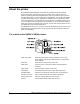
The inside of the printer Film Cartridge Holds the retransfer film. Film Cartridge Release Button Press to release and remove the retransfer film cartridge. Card Out Slot Cards removed from the print area exit here. If the optional LM200/LM300 laminator is installed, cards exit the printer and enter the laminator here. Card Stacker Attach the card stacker to the card stacker brackets. Lift Area Use this area to lift the printer when carrying.
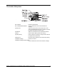
The back of the printer Product Label Find the serial number model, and agency information. USB Port USB 2.0 printer port. Connect a USB printer data cable or a USB smart card cable. Ethernet Port Plug in the Network data cable. Option Label Find a list of the options installed in the printer. The following label shows Duplex, Bend Remedy and Magnetic Encoder options. Cable Guides Secure the data cable to prevent damage. Power Receptacle Plug in the power cord.
About the laminator The Datacard® LM200 or LM300 card laminators are optional laminating modules that work with the SR200 & SR300 printers to add topcoat or patch material to printed cards. Holographic laminating material is available for added security and tamper resistance. A printed card can be laminated manually by simply inserting it into the laminator, or automatically by transferring the printed card from the printer to the laminator module.
The left and right sides of the laminator Card Out Slot Cards exit the laminator here. Card Stacker Attachment Slots Attach the card stacker here. Filter Cover Filter for the air intake. Lift Area Use this area to lift the laminator when carrying. Card Input Slot Cards enter the laminator here. Infrared Window Sends or receives data via infrared communication to the card printer.
Using the printer 2 This section describes how to perform basic tasks required to operate the Datacard® SR200 & SR300 printer and the Datacard® LM200 & LM300 card laminator.
Load Supplies Load cards Tips: Handling cards The card hopper can hold up to 100, .030” (.75mm) cards. The cards are held in position with a hopper cover. Make sure that magnetic stripe or smart cards are loaded in the proper orientation for processing. • Do not touch the surface of cards before printing them. (Oils on hands will reduce printing quality.) • Handle cards by the edges or wear supplied cotton gloves. • Cards can stick together. Slide or fan cards to separate the edges.
Remove Hopper and Cards The card hopper can be removed from the printer for secure storage, to set card thickness, or for cleaning. 1 Slide the card hopper latch closed (1). 2 Lift the hopper up (2). The hopper cover and hopper are locked together and both are removed. 1 Insert the hooks on the card hopper into the slots in the receptacle. 2 Slide the card hopper down until it clicks into place.
Load ink ribbon Tips: Handling ink ribbon • Do not touch the printing surface of the ink ribbon. (Oils on hands will reduce printing quality.) • Place the cartridge on a smooth level surface when loading or reloading. • Do not place the cartridge on the printer door to prevent damage to the door. • Keep unused ink ribbon in the original package until ready for use. • Initialize the ink ribbon each time you remove and replace the ink ribbon cartridge.
Load retransfer film Tips: Handling retransfer film 1 • Place the cartridge on a smooth level surface when loading or reloading. Slide the door latch up and open the printer door. 2 • Do not place the cartridge on the printer door to prevent damage to the door. Press the retransfer film cartridge eject button and remove the green cartridge. 3 Remove both used film spools from the cartridge (if present). • Do not touch the printing surface of the retransfer film.
Load top side laminate film Tips: Handling patch or topcoat material • When you power on the laminator, the patch or topcoat material initializes automatically. 1 Open the laminator door by pulling the top of the door toward you. 2 Remove the top and bottom side film cartridges. 3 Press the laminator cartridge eject button and remove the laminator cartridge carefully. The material must be tight when removing the cartridge. 4 Remove the used material (if present).
Load bottom side laminate film Tips: Handling patch or topcoat material • When you power on the laminator, the patch or topcoat material initializes automatically. 1 Open the laminator door by pulling the top of the door toward you. 2 Remove the top and bottom side film cartridges. 3 Press the laminator cartridge eject button and remove the laminator cartridge carefully. The material must be tight when removing the cartridge. 4 Remove the used material (if present).
Power on Check the PC connection The printer and PC are connected when the printer is set up. To avoid receiving error messages on the LCD panel, make sure that all supplies are properly loaded and in position before powering on the printer. Before you begin processing cards, check the following: • The card printer door and card hopper are closed securely. • The USB data cable is securely connected to the printer and the PC.
Optional laminator connection Tips for printer power • When using the optional LM200 or LM300 laminator, check the following: To avoid receiving errors on the LCD panel, make sure that all supplies are properly loaded and in position before powering on the printer. • Wait while the printer initializes. • Follow the guidelines for your organization about when to power the printer on and off. • The printer and laminator are aligned at the IR ports, using the joining plate.
Power on the printer 1 Press the “" symbol on the power switch. 2 The printer powers on. The printer begins initializing. The LCD panel shows "Initializing" while the printer checks and positions the ink ribbon and retransfer film. 3 When operation checks are complete, "Preheating" is displayed on the LCD panel for approximately two minutes while the retransfer roller (and optional bend remedy roller) warm to their operating temperatures. 4 The LCD panel shows "Ready.
Prepare to print cards Initialize the ink ribbon and retransfer film Tips – Initialize supplies • • • One initialize action moves both ink ribbon and retransfer film. To avoid dirt and dust particles that might adhere to the ink ribbon and retransfer film during loading, move (initialize) the supplies one panel set each time a cartridge is removed from the printer and replaced. The printer detects the type of ink ribbon and retransfer film installed. 1 Press the Reset key on the control panel.
Print cards using ID software 1 Follow the instructions for the ID software to capture, format, and save the data for the card. 2 In the software, send cards to the printer (usually, use the Print button). 3 The printer driver receives data for each card, prepares the card for printing, and sends each card to the printer. Print from a PC application 1 Use the page setup feature in the application to set the following: — Set paper or page size to CR80 card or 2.125" x 3.
Encode tab The Encode tab contains settings for using smart card (IC) and magnetic stripe encoding. You can also specify whether to rotate the card after an encoding step. 5 Print the card. • To restore the printer when it is in sleep mode, press Reset and then Enter on the printer LCD panel. The printer uses one set of panels. • Handle unprinted cards by the edges to preserve print quality. Do not touch the print surface with your hands.
20 SR200 & SR300 Printer and LM200 & LM300 Laminator User Guide
Viewing and changing printer settings 3 This section describes how to view and change printer and laminator settings.
Printing Preferences The Printing Preferences dialog box contains the Setup, Print, Encode, Laminate, Configuration, and Version tabs. To open Printing Preferences: 1 Choose Start from the Windows task bar. 2 Do one of the following: — Windows XP and 2000, choose Settings and then Printers (and Faxes). The Printers (and Faxes) window opens. — Windows Vista, choose Control Panel and then Printers. 3 Click once on the printer icon to select it.
Print tab The Print tab contains settings for using the color (YMC), black (K) panels and additional panels of the print ribbon. The tab also contains controls for color adjustment, setting up a look-up table, setting up page split and dithering. See “Page Split” on page 26 for more information. To print text, bar codes, or both using K ink on the side of a card using ink ribbon with YMCK panels, choose Extraction>Only Text. To print black areas of graphics with K ink ribbon, choose Extraction>All.
UV Ink Use the UV Ink dialog to choose how to print the UV ink panel. You can: • Use UV printing on the front of the card, the back of the card, or both. • Extract text of a specific color, which you specify. (White–255, 255, 255 and black–0,0,0 are not allowed.) — The text will be printed using the UV panel with full grayscale intensity (255). — The text will not be printed with the color panels. • Print the contents of a bitmap file, which you specify in the File Information area.
• Specify the number of retransfer panels used to print one side of a card. UV and YMCK inks cannot be transferred in the same area on the same retransfer panel, so this setting determines what data will print. The following table shows the result for data outside the MAC address area and data overlapping the MAC address area.
Page Split Page Split informs the driver that you plan to use a multi-page input document: One page for YMC (color), another page for black (K), and (if you use UV ink) an additional page for a UV panel, in that order. You can specify Page Split for black (K) printing and for UV panel printing. The following shows a 2-page document with YMC and K printing on one side of the card and Page Split chosen for K printing.
Security Erase To use the Security Erase feature, use a YMCK ink ribbon and choose “Security Erase.” Security erase prints a random pattern using the K panel onto the transfer ribbon. This illustration shows a printed card and the ink ribbon used to print it, without using the Security Erase feature. This illustration shows the same printed card and the ink ribbon used to print it, after using the Security Erase feature. This illustration shows the retransfer ribbon after using the Security Erase feature.
Printing Area Settings On the Print tab, click “Enable the Print Area” and click the “Settings” button to define nonprinting areas of a card design. Also use with peel-off (YMCK-PO) ribbon. You can block YMCK printing areas, but the protective layer from the retransfer material will be applied to the card. To maintain quality, use the peel-off feature and peel-off ribbon to remove the retransfer material in magnetic stripe, smart card chip, and hologram areas.
Encode tab The Encode tab contains settings for using smart card (IC) and magnetic stripe encoding (your ID software might specify these settings, which override the Encode tab). You can also specify whether to rotate the card after an encoding step. Only options installed in the printer appear in this tab. See “Magnetic Stripe Encoding” on page 97 for more information on encoding magnetic stripes. Laminate tab The Laminate tab contains settings for the Laminator.
5 In the General tab of the Properties dialog box, choose Printing Preferences. 6 Choose the Configuration tab. 7 Click the box under Enable the Settings. 8 Go to the “Print tab” on page 23 and click the settings button to make settings for the next card. Version tab The Version tab shows the build version of the printer driver. Your service provider might ask you for this information.
4 From the File menu, choose Properties. The Properties window opens. 5 Use the tabs to set up Sharing, Ports, Color Management, Security, and Advanced options. 6 Choose OK to save and close, or choose Cancel to close without saving changes. Status Monitor During the installation, the driver and Status Monitor are installed. The Status Monitor handles bidirectional communication between the printer and printer driver. Use the Status Monitor to view or change most settings.
1 Begin with the printer powered on and attached to the PC. 2 To start the Status Monitor with Administrator Permissions, do the following: — Use the desktop icon if you installed it. OR From the Windows task bar, choose Start>Programs> Status Monitor. — For Windows Vista, right-click the SR-CP Printer Status Monitor icon and choose Run As Administrator. — For Windows XP and 2000, right-click the SR-CP Printer Status Monitor icon and choose Run As...
Printer Status tab The Status tab shows: Icon • The type of ink ribbon, the approximate percentage remaining, and the lot number. • The type of retransfer film and the approximate percentage remaining. • The resettable print count and a Clear button to set it to zero (0). • If a laminator is attached, laminator status appears under the printer status (marked by the rectangle). • The printer name.
Heating Yellow The printer is adjusting the heat roller temperature. Card Loading Card Transporting Contact IC Encoding Non-Contact IC Encoding MG Encoding Printing Retransfer Yellow The printer is issuing cards. The operating status during card issuing is indicated. When the card is issued, the printer goes into Ready state. Power Saving Yellow The printer is in power save mode. To end Power Saving, press the Reset key on the printer and then press the Enter key to initialize the printer.
— Number of Retry, which sets the maximum number of retries when writing or reading magnetic stripe data fails. Default value is 1. — ISO Mode, which sets the power used by the magnetic card encoder. The default is Hi-Co. • A control to enable or disable the buzzer. • A control to set the display contrast. • A control to set the display mode. • A control to change the display counter.
Bend Remedy tab The printer is available with a bend remedy option. Single-sided printing can cause the card to warp, depending on the type of cards you use. If the option is installed, the tab shows: • A matrix for setting the bend remedy time and temperature. Click a square to choose the setting. Click the Update button to send the settings to the printer. • The card type, set on the Media Setting tab.
• Settings to view or change the type and thickness of cards being used. — For Material, choose PET-G, PVC, or PET (0.25mm). The recommended values for retransfer speed and temperature (on the “Retransfer tab” on page 35) change depending on the selected card type. — For Thickness, choose: — Standard for cards 0.76mm (0.030in) thick — Thin for cards 0.25mm (0.010in) thick — Click the Update button to send the settings to the printer. • A setting to view the type of Retransfer film.
Laminator tab The Laminator tab is enabled if a laminator is connected to the printer. Use the settings on this page to adjust lamination for best results. See “Laminator Settings” on page 60 for examples of settings for single-sided and double-sided lamination. The Laminator tab shows: • Basic Settings: — Laminate Mode: Laminate or Pass Through. — Choose Laminate to laminate a card. — Choose Pass Through to skip lamination. — HR Control: Enable or Disable.
Printer Select tab The Printer Select tab shows: • The currently selected printer. • The unit number. (Use the LCD panel to set the unit number, described in “Using the Printer LCD Panel” on page 51.) • If more than one SR-CP printer is installed on the PC, you can change the printer for which information is displayed by choosing it from the Current Printer list. The Status Monitor will communicate with the printer to update information.
Others tab The Others tab shows the following for a USBconnected printer: • Controls for printing a test card. The printer will create one test card, using the internal test pattern. • Controls for selecting a firmware file and sending it to the printer. Only update printer firmware when your service provider recommends it. For both USB-connected and Ethernet-connected printers, the tab shows: • Version information for the Status Monitor.
6 Click the Update button to activate the security lock and prevent access to the supplies in the printer. Tips for Success • Write down the password and store it in a safe place. • Do not forget the password. You can ask your service provider for assistance, but this is not covered by the warranty. • The Status Monitor password and the security number entered on the printer panel are not linked. You can use different values for these items.
Error Code Displayed Message Solution 0102FD00 The printer is in the Power Saving mode. Resetting the printer temporarily cancels the Power Saving mode. The printer resets automatically when the printer driver is used to start printing. 0102FE00 Password authentication is not complete. — 0102*** The printer is not ready. — 01039000 Failure occurred during card loading. 1 Switch off the printer power. 2 See “Hopper jam” on page 72 to remove the card. 3 Switch on the printer power.
Error Code Displayed Message Solution 0103AD00 An error has occurred during magnetic encoding data writing. Check the card specifications. 0103AE00 An error has occurred during magnetic encoding data reading. Check the card specifications. 0103B000 An incorrect ink ribbon is installed. Install a correct ink ribbon. 0103B000 An incorrect ink ribbon is installed. Install a correct ink ribbon. 0103B100 Ink ribbon is broken.
Error Code Displayed Message Solution 0104F000 The temperature of the retransfer heating roller is too high. 0104F100 The retransfer heating roller is faulty. Turn the power off and on again. If the same problem recurs, turn off the power and contact your service provider. 0104F200 The thermistor of the retransfer heating roller is faulty. 0104F300 The temperature of the bend remedy heating roller is too high. 0104F400 The bend remedy unit is faulty.
Error Code Displayed Message Solution 0142A200 Retransfer film has run out. 1 Load the Retransfer Film (see “Load retransfer film” on page 11). 2 Press Reset and then Enter to initialize the printer. 0142B200 Ink ribbon has run out. 1 Load the Ink Ribbon (see “Load ink ribbon” on page 10). 2 Close the printer door and press Reset and then Enter to initialize the printer. 02****** Printer is not found. • • 05000050 Failure occurred during card loading.
Error Code Displayed Message Solution 05000060 Thermostat is broken. • 05000061 The temperature of the top side Heat Roller is too high. Turn off the power and turn it on again. If the same problem occurs, consult an authorized dealer or service personnel. 05000062 The temperature of the bottom side Heat Roller is too high. 05000063 The internal temperature of the top side Heater is too high. 05000064 The internal temperature of the bottom side Heater is too high.
The following errors are detected by the driver and displayed in a message box. Error Code Displayed Message Solution 02****** Printer is not found. • • 0300274D 0300374D Printer is not found. • • • 03****** Make sure that the host PC and the printer are connected properly. Make sure that the printer is switched on. Make sure that the host PC and the printer are connected properly. Make sure that the printer is switched on.
Error Code Displayed Message Solution 10000504 An error has occurred during magnetic encoding data reading. Check the card specifications. 10000505 A magnetic encoding command error has occurred. Contact your service provider. 10000601 End notification program is not found. Contact your service provider or application provider. 10000603 An error is returned for the end notification program. Contact your service provider or application provider. 10001001 Ink ribbon cannot be recognized.
Using the LCD Menus About the Printer Display Panel The printer LCD panel has 2 lines of text, indicators for key functions, and symbols for connection type and lock status. • Line one of the display shows the current printer status, such as Ready or Printing. It also shows the menu name when using menus. • Line 2 shows card counts or choices available if you are using menus. It also shows the status of the laminator.
The printer is unlocked. The printer is locked. The laminator is connected to the printer. Keys: The indicators for key functions are white text on a black rectangle. The Cleaning display shows how indicators describe the keys. Keys can be: 50 Reset Initializes the printer. Use the Reset key after loading supplies, to end Power Saving, or after an error occurs. Menu Press Menu to use the printer menus.
Reset Initializes the printer. Use the Reset key after loading supplies, to end Power Saving, or after an error occurs. Scroll Right Move the cursor one position to the right. Scroll Left Move the cursor one position to the left. Speaker Provides an electronic beep that indicates: • An error has happened. • Confirms that settings have been saved. The speaker function can be turned on or off using the Status Monitor.
Menu Display Settings Download Function To prepare the printer for a firmware download, press the Enter key. The firmware must be downloaded from a USBconnected PC with the driver and Status Monitor installed. See “Others tab” on page 40 for the Status Monitor page. DO NOT power off the printer while the firmware is being downloaded. Transport Mode OK? Set the Transport Mode when moving or shipping the printer. Press the Return key to use the transport mode.
Menu Display Bend Remedy Heat Roller Settings Function Standby Front Wait Back Wait Displays the value set using the Status Monitor. Backside Cool On Off Displays the value set using the Status Monitor. Temp Level Displays the value set using the Status Monitor. See “Bend Remedy tab” on page 36 for more information. Speed If installed, displays the value set using the Status Monitor. See “Bend Remedy tab” on page 36 for more information.
Menu Display Settings Function MG None Lo-Co Hi-Co Displays the coercivity for writing data to ISO magnetic stripe cards (if a magnetic stripe option is installed): Lo-Co: 238 x 102 [A/m] (300[Oe]) Hi-Co: 218 x 103 [A/m] (2750[Oe]) IC Antenna None Installed Displays whether the contactless card option is installed: • None for no antenna. • Installed when a smart card antenna is used. IC Contact None ISO Type Displays whether the contact card option is installed: • None for no contact.
Menu Display Settings Function HR-T Temp 90 degC to 180 degC Displays the set point temperature of the top heat roller. (The temperature may be 185 degC or higher depending on the firmware version of the card printer.) HR-B Temp 90 degC to 180 degC Displays the set point temperature of the bottom heat roller. (The temperature may be 185 degC or higher depending on the firmware version of the card printer.) Speed 3.0 mm/s to 12.0 mm/s Displays the card speed during lamination.
Menu Display Settings Function Subnet Mask The default Subnet Mask of the printer is 255.255.255.0. If you do not use DHCP, ask your network administrator for the Subnet mask. Gateway The default Gateway of the printer is 192.168.0.1. If you do not use DHCP, ask your network administrator for the Subnet mask. Effective IP The IP address the printer uses. Adrs Config Auto Manual Method to set the IP address if the network uses IPv6.
Printer Security Number The printer can have a security key (number) which can lock and unlock the printer using the LCD panel. If a laminator is installed, this setting also locks the laminator. Set Up 1 Press the middle key for at least three seconds. When you release, “Set Sec-Key OK?” is displayed. 2 Press the Return key. 3 Enter the security number: — The number can be up to 8 digits. — The first digit entered is the left-most digit. — You can move to the right only.
About the Laminator Operator Panel The status of the laminator is displayed on the LCD panel of the card printer and the Status Monitor of the PC connected to the card printer. Red Status Light The red status light indicates an error when only the red light is blinking or lit. Blue Status Light The blue status light indicates that the laminator is functioning normally when only the blue status light is blinking or lit.
Laminator Status Red Status Light Initializing Off Preheating Blue Status Light Card Printer LCD Panel Description Blinking (Slow) Initializing... Initializing in progress. Off Blinking (Slow) Preheating... Adjusts the heating roller to the preset temperature. Low temperature standby mode Off Blinking (Slow) Standby In HR control mode. Power-saving mode Off Blinking (Slow) Sleeping Low power standby mode. Operates together with the card printer settings.
Laminator Settings The Laminator settings to use change with the side of the card printed and the side of the card laminated. The following tables show examples of settings to use. The settings assume that you use heat-resistant PET-G cards, and operate the printer and laminator within the environmental specifications. Make changes in small steps and test results. Double-sided printing and double-sided lamination Film Laminator LM300 Card Printer SR300 1mil 0.
Taking care of your printer This chapter provides information to help you maintain the Datacard® SR200 & SR300 printer and the Datacard® LM200 & LM300 card laminator for optimal performance.
Cleaning the printer This section provides information on proper care and cleaning of the SR200 & SR300 printer. It also includes recommendations on how often to clean and replace components. Cleaning the cleaning unit Tips – Card cleaning roller • Wash the card cleaning rollers regularly, such as every time you change the ink ribbon. The cleaning unit is located inside the printer door and cleans lint and other debris from the cards before printing. To clean the unit: 1 Open the printer door.
Cleaning the card feed rollers and heat roller The heat roller provides the heat used during the retransfer process. The card feed rollers move the card inside the printer. See “Printer roller layout” on page 71 to find the location of the rollers. Tips – Cleaning card feed and heat rollers • • • • The heat roller cannot be cleaned while hot. Power the printer off and allow it to cool, or perform cleaning before the heat roller reaches operating temperature.
Cleaning the magnetic head When printing magnetic stripe cards, the magnetic head should be cleaned every 1,000 cards. If you are not using magnetic stripe cards, the magnetic head does not require cleaning. Tips –Magnetic head cleaning card • Replace the magnetic head cleaning card when it becomes dirty. Using a dirty magnetic head cleaning card can damage the magnetic head. Begin with the printer (and optional laminator) powered off. 1 Power on the printer. See “Power on the printer” on page 16.
Cleaning the thermal head The thermal head assembly should be cleaned once every ten rolls of retransfer film. Begin with the printer (and optional laminator) powered off. Tips – Thermal head • Do not use metal or other abrasive materials to clean the thermal head. • The thermal head can be damaged by an electrostatic charge. Discharge yourself by touching the printer frame before cleaning the thermal head. 1 Open the printer door.
Preparing the printer and laminator for transport Use saved packaging materials to prepare the printer and optional laminator for transport. Transport includes moving the printer from one location to another within the same facility. 1 Open the door to the printer. The “Door Open” error message is displayed. 2 Remove the printer ink ribbon cartridge and remove the ink ribbon from the cartridge. Replace the empty cartridge into the printer.
Cleaning the laminator Most card jams are caused by dirty rollers. Clean the laminator at the same time that you clean the printer. If you are using the laminator as a stand-alone unit, clean the laminator after every 1,000 cards. Cleaning the card feed rollers and heat roller The heat roller provides the heat used during the retransfer process. The card feed rollers move the card inside the laminator. See “Laminator roller layout” on page 80 to find the location of the rollers.
Cleaning the laminator internal components Dirt during card feed or burrs caused by friction between the bobbin holder and bobbin can adhere to the card or film, causing defections in card lamination. Clean these components regularly to avoid lamination defects. 1 Begin with the laminator turned off. 2 Open the laminator door. 3 Remove the top laminate film cartridge and the upper cover or bottom laminate film cartridge.
Cleaning the laminator cartridge The laminator cartridge(s) can collect debris and dust during lamination and supply loading. Clean the cartridge(s) every 1,000 cards. 1 2 3 4 5 6 7 Open the laminator door by pulling the top of the door toward you. Press and hold down the cartridge release button and pull out the film cartridge. Remove the laminate film from the film cartridge. Clean the four metal guides with a lint free cloth and isopropanol. Replace the supply and take-up spools on the cartridge.
70 SR200 & SR300 Printer and LM200 & LM300 Laminator User Guide
Messages and error recovery 5 This chapter provides information to help you respond to the printer and laminator messages and explains how to recover from an error. It describes: • “Printer roller layout” on page 71 • “Printer error recovery” on page 72 • “Printer LCD messages” on page 77 • “Laminator roller layout” on page 80 • “Laminator LCD messages” on page 84 Printer roller layout * Optional features If the printer uses the Security Lock, see “Security Lock tab” on page 40.
Printer error recovery The printer’s LCD panel background color changes to red when the printer has an error. The LCD panel displays text that describes the error. Hopper jam If a card jams in the card hopper section, “Jam (Hopper)” is displayed on the LCD panel. To remove the jammed card: 1 Slide the card hopper latch open. 2 Slide the card cover up and remove any cards. 3 Try the following in the order presented: a Tips – Hopper jam • If you can reach the jammed card, pull it out.
Transfer jam Tips – Transfer jam • Some internal parts may be hot. Wear a glove when reaching into the printer. If the card jams in the card feed rollers, “Jam (Transfer)” is displayed on the LCD panel. To remove the jammed card: 1 Power off the printer. 2 Remove the card hopper and cards. See “Remove Hopper and Cards” on page 9. 3 Locate the jammed card. 4 Place one Jog Dial on the cleaning unit shaft and the other Jog Dial on the card feed rollers shaft.
Turnover jam Tips – Turnover jam • Some internal parts may be hot. Wear a glove when rotating the turnover unit. If a card jams in the card turnover section, “Jam (TurnOver)” is displayed on the LCD panel. To remove the jammed card: 1 Power off the printer. 2 Remove the card hopper and cards. See “Remove Hopper and Cards” on page 9. 3 Remove the slot cover. 4 Open the printer door. 5 Remove the cleaning unit. 6 Remove the jammed card from the turn-over unit, through the slot in the input area.
Retransfer section jam Tips – Retransfer jam • • • Some internal parts may be hot. Be careful when removing a jammed card. The card might be very hot. Use the supplied tweezers to remove cards from the printer. If a card jams in the retransfer section, “Jam (Retransfer)” is displayed on the LCD panel. To remove the jammed card: 1 Power off the printer. 2 Open the printer door. 3 Press the retransfer film cartridge eject button and remove the retransfer film cartridge.
Mending broken ink ribbon or retransfer film If the ink ribbon or retransfer film breaks, “Ink Search” or “Media Search” is displayed on the LCD panel. Broken ink ribbon is shown in the following example; repairing broken retransfer film uses the same steps. 1 Power off the printer. 2 Open the printer door. 3 Press the eject button for the appropriate cartridge and remove the cartridge. 4 Trim the ends of the broken portions evenly. Do not remove the used ink ribbon or film from the take-up spool.
Printer LCD messages LCD Message Possible Cause Solution Please, Power Off The power must be turned off to initialize the printer. Turn the power switch off and then on again. Please Remove Media Cassette Cleaning cannot start when the retransfer film cartridge is in the printer. 1 Remove the retransfer film cartridge. 2 Press Reset and then Return to initialize the printer. 3 Start the cleaning cycle again.
LCD Message Possible Cause Solution Jam (Retrans) There is a card jam near the retransfer rollers. 1 Remove the jammed card from the retransfer section. 2 Press Reset, and then Return to initialize the printer. 3 See “Retransfer section jam” on page 75. Film Search The retransfer film is broken or missing. 1 Repair the retransfer film as described in “Mending broken ink ribbon or retransfer film” on page 76. 2 Press Reset, Next, and then Return to initialize the film one panel.
LCD Message Possible Cause Solution HR Overheat The retransfer or bend remedy roller is too hot. Turn the power switch off and then on again. Call for service if the problem persists. TR Heater The retransfer roller is not working. Turn the power switch off and then on again. Call for service if the problem persists. TR Overheat The retransfer roller is too hot. Turn the power switch off and then on again. Call for service if the problem persists.
Laminator roller layout Laminate pressure motor Take-up side Supply side Laminator error recovery The printer LCD panel and the Status Monitor displays laminator messages. See “Laminator LCD messages” on page 84 for a list of messages. Card jam The printer LCD panel displays the location of the card jam: Card Jam (In), Card Jam (Middle), or Card Jam (Out). Use the following steps to remove card jams. 80 1 Open the laminator door.
attached to the laminate film. Pull out the cartridge slowly to avoid dropping the laminate film from the cartridge. If the cartridge cannot be removed, call for service. 4 Remove the jog dial from the card printer and attach it to the jog dial insertion slot. 5 Turn the jog dial counterclockwise to discharge the card from the card outlet.
Patch Position The position of the patch on the card can very slightly with a different lot of laminator supply material. You can change the left-to-right position or the top to bottom position. Change the front-to-back position Turning the supply sprocket of the film cartridge enables you to adjust the patch position to the front or back by 1.0 mm. Use the following steps to change the front-to-back patch position: 1 Power off the laminator and allow it to cool.
— Moving the slider to the left moves the patch to the left side of the card. — Moving the slider to the right moves the patch to the right side of the card. 3 Select Update to update the laminator settings. 4 Laminate a card to verify the new position. Card warping When the laminated card warps, the optional printer bend remedy can correct the problem. See “Bend Remedy tab” on page 36.
Laminator LCD messages LCD Message Possible Cause Solution Jam (In) There is a card jam in the entrance area. Check that the laminator is properly connected to the printer as described in “Optional laminator connection” on page 15. See “Card jam” on page 80 to clear the jam. Jam (Middle) There is a card jam near the heating roller. The laminating temperature is too high or the speed is too slow. Set the temperature or speed as described in “Laminator tab” on page 38.
LCD Message Possible Cause Solution HR-T Overheat Heating roller temperature error (temperature is too high). Turn the power switch off, and then back on. Contact your service provider if this does not correct the condition. Overheat-T Internal temperature error (temperature is too high). Turn the power switch off, and then back on. Contact your service provider if this does not correct the condition. Heater-B Heater error. Turn the power switch off, and then back on.
LCD Message Possible Cause Solution Overcool Internal temperature error (temperature is too low). The ambient operating temperature is too low. Use the laminator within the prescribed range. When starting up the laminator in a low temperature environment, the temperature of the interior can remain low even though the surrounding temperature has gone up. Turn on the power again after waiting for about one hour. Supply ENC-B Supply side motor encoder (rotation detection) error.
Supplies This section outlines the recommended supplies to use with the Datacard® SR200 & SR300 card printer and the Datacard® LM200 & LM300 card laminator.
Ink ribbon, and retransfer film, and laminator material Ink ribbon Color print ribbons are designed for full-color card printing. The ribbons use the following color panels: Y=yellow, M=magenta, C=cyan, and K=black.
Laminator material Successful laminating depends on the type of card used and its construction. If you are interested in applying topcoat or patch on PVC cards, contact your dealer for guidance. Datacard® provides two types of materials for use in laminators: • Topcoat, which is a continuous film. • Patch, which has die-cut patches sized to fit on a card. The LM200/LM300 laminator can apply any of the following types of laminator supply materials: Patch material 0.
Card size Use ISO-1 (CR-80) size cards with the following nominal dimensions: Length 3.375 inches 85.60 mm Width 2.125 inches 53.98 mm Thickness 0.010 to 0.040 inches 0.25 to 1.0 mm The default card thickness is 0.030in (0,75mm). The card hopper and printer can be set for other supported thinknesses. Contact your service provider before using 0.010in (0.25mm) thick cards. Tips for success PVC cards less than 0.027 inches are not recommended.
Site requirements This section describes the operating environment recommended for your Datacard® SR200 & SR300 card printer and Datacard® LM200 & LM300 card laminator.
Site guidelines When choosing a site for the printer and its supplies, consider these guidelines: Tips – Site selection • Keep all dust, dirt, food, liquids, etc. away from the printer at all times. • Avoid locating the equipment in dirty or dusty environments. Do not use supplies or cards that have been dropped on the floor or have otherwise become contaminated. • Keep paper and foreign materials off the printer. • Do not place in areas susceptible to strong vibration or shock.
Ventilation clearance To ensure proper ventilation to the printer and laminator, maintain minimum clearance distances as shown. Sides: 8” (20cm) Back: 4” (10cm) • Keep paper and foreign materials off the printer. • Place the printer on a stable platform • Do not place in areas susceptible to strong vibration or shock. • Keep all dust, dirt, food, liquids, etc. away from the printer at all times.
Printer specifications Recording method: Dye Sublimation Retransfer Feed format: Automatic feed Recording density: 300 dpi Reproduction gradations: 256 levels each yellow (Y), Magenta (M), & Cyan (C); 2 for Black (K) Printing time: 29 sec. (single sided, excluding data transfer time) Interface: USB 2.
Laminator specifications Transfer method Halogen lamp built-in heat roller method Transfer time About 20 seconds, depending on settings used. Usage environment Temperature: 59° F to 86° F (15° C to 30° C) Storage environment Temperature: Humidity: 5° F to 131°F (-15° C to 55° C) 30% to 80% (without condensation) Power supply: Power consumption: 100-120VAC or 220-240VAC (±10%) Approximately 190W Weight: 20.9 lbs (9.5 kg) Sound level: Less than 70dB(A) according to DIN45635, part 19 (EN27779).
96 SR200 & SR300 Printer and LM200 & LM300 Laminator User Guide
Magnetic Stripe Encoding This section provides information about encoding magnetic stripe data.
Inline Encoding When the Magnetic Encode setting on the Printing Preferences Encode tab is checked, the magnetic stripe encoder can be enabled. The encoding data is sent to the card printer through the printer driver using the prefix characters described in this section. This function is called “inline encoding”. If the first three characters in a line are prefix characters (Tilde, “?” and numeral), the text that follow is recognized as encoding data. Encoding data is not printed on a card.
Character Code Table The following table shows the usable ASCII character codes. The encoding data must use only allowed characters. b7 b6 b5 b4 0 0 0 0 0 0 0 0 1 1 1 1 1 1 1 1 b3 0 0 0 0 1 1 1 1 0 0 0 0 1 1 1 1 b2 0 0 1 1 0 0 1 1 0 0 1 1 0 0 1 1 b1 0 1 0 1 0 1 0 1 0 1 0 1 0 1 0 1 0 1 2 3 4 5 6 7 8 9 A B C D E F 0 0 0 0 0 0 1 1 LF 0 1 0 2 ! “ # $ %* & ‘ ( ) * + , .
100 SR200 & SR300 Printer and LM200 & LM300 Laminator User Guide
Compliance (FCC) This section describes the regulatory compliance of the Datacard® SR200 & SR300 printer and the Datacard® LM200 or LM300 laminator.
Regulatory compliance Notice for USA (FCC notice) This equipment generates, uses, and can radiate radio frequency energy. If it is not installed and used in accordance with this instruction manual, it may interfere with radio communications. This equipment has been tested and found to be within the limits for Class A computing devices, pursuant to Subpart J of Part 15 of FCC rules, designed to provide reasonable protection against radio interference in a commercial environment.
11111 Bren Road West Minnetonka, MN 55343-9015 952.933.1223 952.933.7971 FAX www.datacard.com The design and information contained in these materials is protected by US and international copyright laws and treaties.