
User manual


Tasks and Kits
3-10 ProMaster 2500 User Manual
Note: Your company should establish a standard orientation for each device
package type (DIP, square PLCC, 32-pin PLCC, SOIC) so that all
operators insert devices correctly. All devices are inserted and handled
upside-down (also known as “dead bug”) on the 2500.
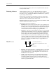
The arrows on the TaskLink screen point to the four sides of the device
(see Figure 3-7). Move the cursor using the
↑
and
↓
keys. Press
T
AB
when
you have the correct orientation highlighted for the Output
track.
TaskLink then prompts you for the Label and Input orientation fields.
Install all devices upside-down in the 2500 so that their leads are pointing
toward the ceiling (dead bug). We recommend the following default
positions for pin 1 (see Figure 3-8):
• DIP devices: Pin 1 is to the right side, closest to the input tube.
• 32-pin PLCC devices: Pin 1 is to the right side, closest to the input
tube.
• Square PLCC devices: Pin 1 is pointing to the back of the 2500.
Figure 3-7
Selecting Orientation of Device
Pin 1 in the Input Tube Using
TaskLink
SQUARE PLCC
INPUT TUBE
INPUT
INPUT
TASKLINKPACKAGE
DIP, SOIC, and
32-PIN PLCC
TO 2500
TO 2500
1889-2